


-
TU531, I/O terminal unit, 120/230 V AC, screw terminals
-
TU532, I/O terminal unit, 120/230 V AC, spring terminals
-
TU532-XC, I/O terminal unit, 120/230 V AC, spring terminals, XC version
-
TU532-H, I/O terminal unit, hot swap, 120/230 V AC, spring terminals
-
TU532-H-XC, I/O terminal unit, hot swap, 120/230 V AC, spring terminals, XC version
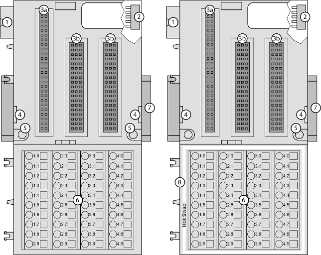
1
I/O bus (10 pins, male) to connect the previous terminal unit, the CPU terminal base or the communication interface module to the terminal unit
2
I/O bus (10 pins, female) to connect other terminal units
3a
Plug (2 x 25 pins) to connect the inserted I/O modules
3b
Plug (3 x 19 pins) to connect the inserted I/O modules
4
With a screwdriver inserted in this place, the terminal unit and the adjacent I/O terminal unit can be shoved from each other
5
Holes for screw mounting
6
40 terminals for signals and process supply voltage
7
DIN rail
8
White border signifies hot swap capability of the terminal unit
The input/output modules (I/O modules) plug into the I/O terminal unit. When properly plugged-in, they are secured with two mechanical locks. All the connections are established via the terminal unit, which allows removal and replacement of the I/O modules without disturbing the wiring at the terminal unit.
The terminal units TU531 and TU532 are specifically designed for use with AC500/S500 I/O modules that incorporate 115 V AC ... 230 V AC inputs and/or 120/230 V AC relay outputs.
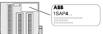
XC version
XC = eXtreme Conditions
Extreme conditions
Extreme conditions
Terminal units for use in extreme ambient conditions have no  sign for XC version.
The figure 4 in the Part no. 1SAP4... (label) identifies the XC version.
Terminals
|
Screw terminals |
Spring terminals |
||||
|---|---|---|---|---|---|
|
Conductor |
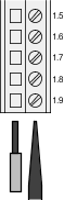 |
Screwdriver |
Conductor |
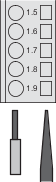 |
Screwdriver (opens terminal) |
The terminals 1.8 ... 4.8 and 1.9 ... 4.9 are electrically interconnected within the terminal unit.
The terminals always have the same assignment, independent of the inserted module:
-
Terminals 1.8 ... 4.8: process supply voltage UP = +24 V DC
-
Terminals 1.9 ... 4.9: process supply voltage ZP = 0 V
The assignment of the other terminals depends on the inserted communication interface module (see the description of the respective module used).
The supply voltage of 24 V DC for the module's circuitry comes from the I/O expansion bus (I/O bus).
-
Technical data
-
Hot swap
-
Dimensions
-
Ordering data