


-
TU509, terminal unit, 24 V DC, screw terminals
-
TU510, terminal unit, 24 V DC, spring terminals
-
TU510-XC, terminal unit, 24 V DC, spring terminals, XC version
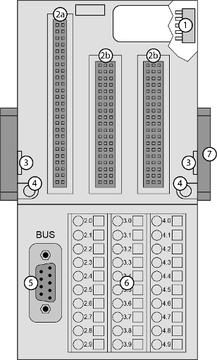
1
I/O bus (10 pins, female) to connect the first terminal unit
2a
Plug (2 25 pins) to connect the inserted communication interface module
2b
Plug (3 19 pins) to connect the inserted communication interface module
3
With a screwdriver, inserted in this place, the terminal unit and the adjacent terminal unit can be shoved from each other
4
2 holes for wall mounting
5
D-sub 9 (female) for connection with the PROFIBUS network
6
30 terminals for signals and process supply voltages (UP and UP3)
7
DIN rail
The communication interface modules plug into the terminal unit. When properly plugged-in, they are secured with two mechanical locks. All the connections are established via the terminal unit, which allows removal and replacement of the communication interface modules without disturbing the wiring at the terminal unit.
The terminal units TU509 and TU510 are specifically designed for use with AC500/S500 communication interface modules (e. g. CI451-DP).
XC version
XC = eXtreme Conditions
Extreme conditions
Extreme conditions
Terminal units for use in extreme ambient conditions have no  sign for XC version.
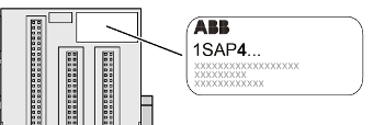
The figure 4 in the Part no. 1SAP4... (label) identifies the XC version.
Terminals
|
Screw terminals |
Spring terminals |
||||
|---|---|---|---|---|---|
|
Conductor |
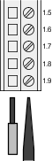 |
Screwdriver |
Conductor |
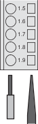 |
Screwdriver (opens terminal) |
The terminals 2.8, 3.8, 2.9, 3.9 and 4.9 are electrically interconnected within the terminal unit and always have the same assignment, irrespective of the inserted module:
Terminals 2.8 and 3.8: process supply voltage UP = +24 V DC
Terminal 4.8: process supply voltage UP3 = +24 V DC
Terminals 2.9, 3.9 and 4.9: process supply voltage ZP = 0 V
The assignment of the other terminals depends on the inserted communication interface module (see communication interface modules for CANopen and PROFIBUS).

NOTICE
Risk of corrosion!
Unused connectors and slots may corrode if XC devices are used in salt-mist environments.
Protect unused connectors and slots with TA535 protective caps for XC devices⮫ “TA535 - Protective caps for XC devices”.
-
Technical data
-
Dimensions
-
Ordering data