


-
TA5400-SIM input simulator for 6 digital inputs 24 V DC
-
For usage with AC500-eCo processor modules
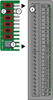
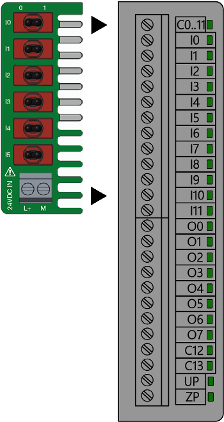
1
Contacts for connecting the input simulator to the terminal block for I/O connectors
2
6 switches for the digital inputs DI0 ... DI5 (0 means opened switch, 1 means closed switch)
3
Screw terminal block for power supply
4
Screw terminal block(s) for I/O connectors
Intended purpose
TA5400-SIM
TA5400-SIM
The TA5400-SIM input simulator is only intended for testing and training purposes for AC500-eCo processor modules PM50x2.
Continuous operation in a productive system is not permitted.
The TA5400-SIM input simulator may only be used with screw-type terminal blocks.
The TA5400-SIM input simulator must not be used with spring-type terminal blocks.
Environmental conditions for testing and training purposes
Environmental conditions for testing and training purposes
In order not to impair the functionality of the product, avoid any kind of disturbing environmental influences:
-
mechanical disturbances
-
climatic influences
Make sure that the parameters are within the normal range:
-
temperature
-
air pressure
-
humidity
-
altitude
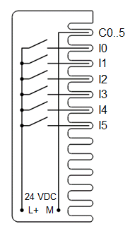
The TA5400-SIM input simulator can simulate 6 digital 24 V DC input signals to the digital inputs I0 ... I5 of onboard I/Os.
With the TA5400-SIM input simulator, the digital 24 V DC inputs I0 ... I5 can be turned OFF and ON separately:
-
If the lever of the switch is on the right side (1), the input is ON.
-
If the lever of the switch is on the left side (0), the input is OFF.
Dimensions
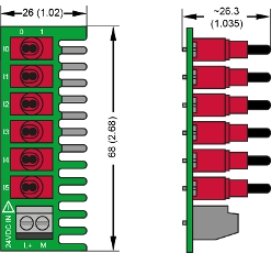
The dimensions are in mm and in brackets in inch.
Electrical diagram
The diagram below shows the connection of the TA5400-SIM input simulator.

NOTICE
Risk of damage to the TA5400-SIM input simulator!
Do not remove the terminal block while the TA5400-SIM input simulator is connected.
Do not apply mechanical forces to the input simulator when it is connected to the terminal block.
In both cases the input simulator could be damaged.
Assembly
Insertion of the input simulator
-
Make sure that the power supply of the processor module is turned off.

CAUTION
Risk of damaging the PLC modules!
The PLC modules can be damaged by overvoltages and short circuits.
Make sure that all voltage sources (supply and process voltage) are switched off before working on the system.
CAUTION
Risk of damaging the input simulator and the PLC modules!
-
Never connect voltages > 24 V DC to the terminal block of the input simulator.
-
The input simulator may only be used with AC500-eCo processor modules PM50x2.
Never use the input simulator with other devices.
-
The input simulator may only be used with screw-type terminal blocks.
-
The input simulator is only intended for testing and training purposes.
Never use it within productive sytems.
-
-
Make sure that all clamps of the onboard I/Os are totally open.
-
Insert the TA5400-SIM input simulator into the screw terminal block as shown in the figure.
-
Tighten all screws of the onboard I/O clamps.
-
Make sure all switches are in OFF state (0).
-
Connect 24 V DC to the power supply of the TA5400-SIM (L+ and M). Tighten the screws.
-
Connect the processor module power supply wires (24 V DC)⮫ “Pin assignment”.
Disassembly
Removal of the input simulator
-
Make sure that the power supply of the processor module is turned off.
CAUTION
Risk of damaging the PLC modules!
The PLC modules can be damaged by overvoltages and short circuits.
Make sure that all voltage sources (supply and process voltage) are switched off before working on the system.
-
Disconnect the TA5400-SIM power supply wires (24 V DC) with a flat-blade screwdriver from the terminal block for power supply (L+ and M).
-
Loosen all screws of the onboard I/Os.
-
Remove the input simulator by pulling it to the left side.
Technical data
The system data of AC500-eCo apply ⮫ “System data AC500-eCo”
Only additional details are therefore documented below.
|
Parameter |
Value |
|
|---|---|---|
|
Process supply voltage |
||
|
Connections |
Terminal (L+) for +24 V DC and terminal (M) for 0 V DC |
|
|
Rated value |
24 V DC |
|
|
Max. ripple |
5 % |
|
|
Weight |
18 g |
|
|
Mounting position |
Horizontal or vertical |
|
Ordering data
|
Part no. |
Description |
Product life cycle phase *) |
|---|---|---|
|
1SAP 187 600 R0001 |
TA5400-SIM, input simulator for PM50x2 |
Active |
*) Modules in lifecycle Classic are available from stock but not recommended for planning and commissioning of new installations.