


CAN interfaces
|
Terminal block for CAN |
Terminal |
Signal |
Description |
|---|---|---|---|
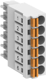 |
1 |
H1 internally connected to H2 |
Bus line, receive/transmit line, HIGH |
|
2 |
L1 internally connected to L2 |
Bus line, receive/transmit line, LOW |
|
|
3 |
GND |
CAN reference potential |
|
|
4 |
H2 internally connected to H1 |
Bus line, receive/transmit line, HIGH |
|
|
5 |
L2 internally connected to L1 |
Bus line, receive/transmit line, LOW |
|
|
6 |
GND |
CAN reference potential |
Protocols
AC500 V3 PLCs provide the following methods for CAN integration:
|
Protocols |
Onboard CAN **) |
CM598-CN(-XC) *) |
|---|---|---|
|
CANopen master |
X |
X |
|
CAN 2A/2B |
X |
X |
|
J1939 |
X |
|
|
CI58x-CN(-XC) (CANopen slave) communication interface module as remote I/O with local I/O connected to a CANopen master |
X |
X |
Remark:
*) only for AC500
Onboard CAN **) interface is available for AC500-eCo V3 CPUs PM50x2 with option board TA5146-CN(W) (except Basic CPUs). Use slot 1 or 2 only.
Supported protocols
Onboard CAN interface supports the following protocols
-
CANopen master
-
CAN 2A/2B
-
J1939
Configuration in Automation Builder is described in chapter 'CANopen'⮫ “CM598-CAN - CANopen Manager communication module”.
Further information can be found in chapter 'CAN onboard'⮫ “CAN onboard”.
Types of bus cables
For CANopen, only bus cables with characteristics as recommended in ISO 11898 are to be used. The requirements for the bus cables depend on the length of the bus segment. Regarding this, the following recommendations are given by ISO 11898:
|
Length of segment [m] |
Bus cable (shielded, twisted pair) |
Max. transmission rate [kbit/s] |
||
|---|---|---|---|---|
|
|
Conductor cross section [mm²] |
Line resistance [W/km] |
Wave impedance [W] |
|
|
0...40 |
0.25 ... 0.34 / AWG23, AWG22 |
70 |
120 |
1000 at 40 m |
|
40...300 |
0.34 ... 0.60 / AWG22, AWG20 |
< 60 |
120 |
< 500 at 100 m |
|
300...600 |
0.50 ... 0.60 / AWG20 |
< 40 |
120 |
< 100 at 500 m |
|
600...1000 |
0.75 ... 0.80 / AWG18 |
< 26 |
120 |
< 50 at 1000 m |
Bus termination
The ends of the data lines have to be terminated with a 120 W bus terminating resistor. The bus terminating resistor is usually installed directly at the bus connector.
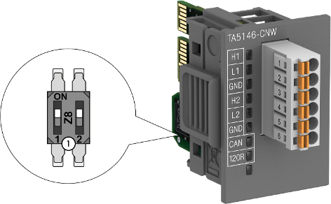
1
Termination resistance settings
Position 1 of the DIP switch activates/deactivates the 120 Ω termination resistor. The position 2 turns ON/OFF the 120R LED
|
Settings on the module |
State of LEDs |
Description |
|---|---|---|
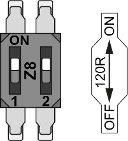 |
 |
Bus termination 120 Ω is activated (Position 1 is ON). Termination LED - 120R is turned ON (Position 2) |
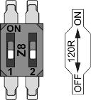 |
 |
Bus termination 120 Ω is deactivated (Position 1 is OFF). Termination LED - 120R is turned OFF (Position 2) |