


-
4 digital outputs 24 V DC (O0 to O3) in 1 group
-
Module-wise galvanically isolated
-
W variant available for use in extended (wide) temperature range
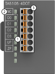
1
4 yellow LEDs to display the signal states at the digital outputs O0 ... O3
2
Allocation of signal name
3
7-pin terminal block for output signals

NOTICE
Risk of damaging the PLC modules!
Overvoltages and short circuits might damage the PLC modules.
Make sure that all voltage sources (supply voltage and process supply voltage) are switched off before you begin with operations on the system.
-
Intended purpose
-
Functionality
-
Connections
-
I/O configuration
-
Parameterization
-
Diagnosis
-
Technical data
-
Dimensions
-
Ordering data