Communication modules are mounted on the left side of the processor module on the same terminal base. The connection is established automatically when mounting the communication module.

NOTICE
Risk of damaging the PLC modules!
Overvoltages and short circuits might damage the PLC modules.
-
Make sure that all voltage sources (supply voltage and process supply voltage) are switched off before you begin with operations on the system.
-
Never connect any voltages or signals to reserved terminals (marked with ---). Reserved terminals may carry internal voltages.
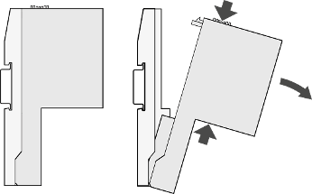
After mounting the terminal base, mount the communication modules.
-
First insert the bottom nose of the communication module into the dedicated holes of the terminal base. Then, rotate the communication module on the dedicated terminal base slot until it is locked in place.
NOTICE
Risk of malfunctions!
Unused slots for communication modules are not protected against accidental physical contact.
-
Unused slots for communication modules must be covered with dummy communication modules to achieve IP20 rating⮫ “TA524 - Dummy communication module”.
-
I/O bus connectors must not be touched during operation.
-
-
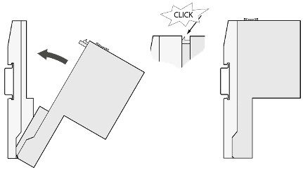
The demounting is carried out in a reversed order.
Press above and below, then rotate the communication module and remove it.