


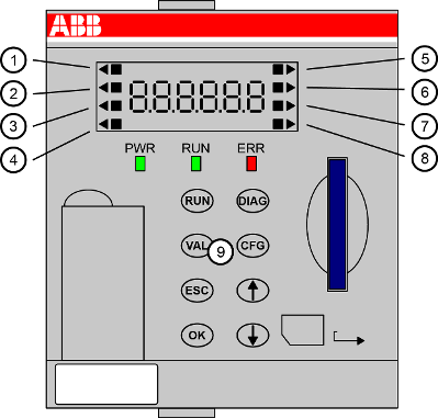
The display of a processor module is equipped with a background-lighted 7-segment display. This display consists of 6 digits for plain text or error codes.
Some functionalities may be not yet supported by the product. Please refer to the release notes of the product at time of release.
Display indicators
-
A black square (
 ) denotes the state/working activity of the corresponding object
on the left/right side of the display. The black square flashes according to
the device's activity, e.g. during data exchange on ETH1, ETH2, COM1, etc.
) denotes the state/working activity of the corresponding object
on the left/right side of the display. The black square flashes according to
the device's activity, e.g. during data exchange on ETH1, ETH2, COM1, etc.
MC activity
MC activity
For the activity of the memory card the black square () is shown as long as a file is open on memory card.
-
A black triangle (
 ) points to the selected item/interface on the left/right
side of the display to be configured or read. Further, it acts as a cursor for the
count up/count down function keys.
) points to the selected item/interface on the left/right
side of the display to be configured or read. Further, it acts as a cursor for the
count up/count down function keys.
A black triangle ( ) at the BATT item indicates a
missing or uncharged battery.
) at the BATT item indicates a
missing or uncharged battery.
|
No. |
On the left side |
Description |
|---|---|---|
|
1 |
MC (memory card) |
Refers to the memory card state. |
|
2 |
SYS (system) |
Refers to the system state. |
|
3 |
BATT (battery) |
Refers to the battery state. |
|
4 |
I/O bus |
Refers to I/O bus connection. |
|
No. |
On the right side |
Description |
|---|---|---|
|
5 |
ETH1 |
Refers to the first Ethernet interface. |
|
6 |
ETH2 |
Refers to the second Ethernet interface. |
|
7 |
COM1 |
Refers to COM1 interface. |
|
8 |
CAN |
Refers to CAN interface. |
|
9 |
Function keys on front panel |
|
Processor module |
Display variant |
Description |
|---|---|---|
|
PM56xx-2ETH |
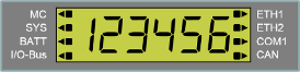 |
Display of a processor module with support for 2 Ethernet interfaces, CAN and COM1. |