


Adding F-series module
-
In the Automation Builder device tree, right-click on device node and select “Add object”.
-
Select “FSeriesIO” and click “Add object”.
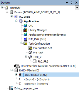
The FSeriesIO extension is added to the project. It contains 3-empty slots. You can add FIO-01, FIO-11, FAIO-01 or FDIO-01 modules to F-Series slots. FDCO adapter is required if you are using FEA-03 module.
You can add only one FDCO adapter to FSeriesIO extension. Because it has only one communication port for FDCO adapter in the firmware.
See parameter 60.41 Extension adapter com port in ⮫ ACS880 Primary control program Firmware manual (AINLX)
-
In the ExtIO (FSeriesIO), right-click on empty slot and click “Add object”.
-
Select FDCO-01/02 adapter and click “Replace object”.
FDCO-01/02 adapter is added to the slot of FSeriesIO module.
-
In the FDCO (FDCO-01/02), right-click on empty slot and click “Add object”.
-
Select FEA-03 and click “Replace object”.
-
In the FEA (FEA-03) module, right-click on an empty slot and click “Add object”.
-
Select FIO-01 module and click “Replace object”.
Similarly, you can add FIO-11, FAIO-01 or FDIO-01 modules to FEA-03 empty slots.
F-series IO modules used in Automation Builder should not be activated as extension IO module in groups 14, 15 and 16 in Drive Composer pro.
Setting module data
Adding node number
-
In the Automation Builder, double-click “FIO_01” or any other module.
-
Click “I/O-Bus Module Parameters ” tab and add the node number in the value field.
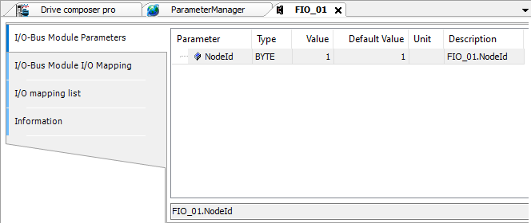
The node numbers 1, 2 or 3 are based on slot numbers. The node numbers 4…10 are used if the I/O module is placed on FEA-03 module.
I/O mapping variables
-
In the Automation Builder, double-click “FIO-01 ”or any other module.
-
Click “I/O-Bus Module I/O Mapping ” tab and create I/O mapping variables in “Variable” column.
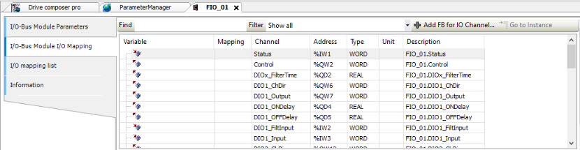
The variable names must be individual. You can have maximum 100 mapping variables. The I/O mapping variables do not support mapping to existing variables.
Using F-series I/O from the application
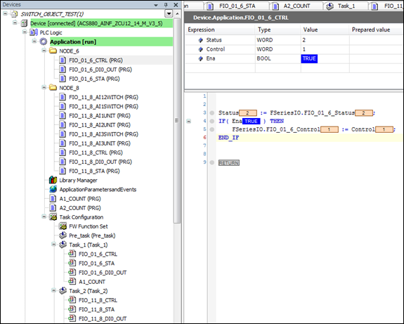
You can assign I/O module related blocks into the same application task. Do not assign F-Series related block into PreTask. The I/O module can be handled according to the fastest task cycle which contains module related blocks.
For example, FIO-01 is using Task_1 cycle and FIO-11 is using Task_2 cycle. If some of the FIO-11 handling blocks are moved into Task_1, then FIO-11 is handled (internally) using Task_1 cycle, regardless, where other FIO-11 blocks are assigned. (Task_1 has fastest cycle).
The IEC variable name must start with F-Series I/O.
The below figure shows the status of the application used for controlling the application execution or producing application based events.
Adding bus fault control
To add F-Series I/O module to Automation Builder project, proceed as follows:
-
In the Automation Builder devices tree, double-click “ExtIO (FSeriesIO)”.
-
Go to I“/O-Bus Module I/O Mapping” tab and create I/O mapping variables in “Variable” column.
FSeriesIO.BUS_Control value should be 0 in a program. The program should store value 1 in FSeriesIO.BUS_Control if the FSeriesIO.BUS_Status value is 3 (no communication). The program should restore value 0 if the FSeriesIO.BUS_Control after the bus break is over when SeriesIO.BUS_Status I/O receives the value 2 (active).
The FSeriesIO.BUS_Status receives the same values as channel status.
-
0 = Not active
-
1 = Initializing state
-
2 = Active
-
3 = No communication
The F-Series I/O bus does not recover automatically after the bus break. The bus can recover without motor stop and restart by using bus control variable.
FIO-01 module data
You can find the general information of FIO-01 module by clicking on “Information ” tab.
|
Channel |
Description |
|---|---|
|
Status |
0 = Not active 1 = Initializing state 2 = Active 3 = No communication |
|
Control |
0 = Inactivate 1 = Activate FIO-01 module |
|
DIOx_FilterTime |
Defines the filtering time constant (0.8…100.0 ms). This time is applied for all the filtered inputs (optional). |
|
DIOx_ChDir (x=1-4) |
0 = DIO is used as a digital output (default value). 1 = DIO is used as a digital input. |
|
DIOx_Output (x=1-4) |
1/0 = ON/OFF status of digital output if channel is used as output (ChDir= 0). The corresponding ON and OFF time delays are applied if they are defined. |
|
DIOx_ONDelay (x=1-4) |
Defines activation delay (0.0…300.0 s) applied for digital input/output. This channel is optional. |
|
DIOx_OFFDelay(x=1-4) |
Defines deactivation delay (0.0…300.0 s) applied for digital input/output. This channel is optional. |
|
DIOx_FiltInput (x=1-4) |
1/0 = ON/OFF status of digital input if channel is used as input (ChDir= 1). Filter time is applied if it is defined. Time delays are never applied. |
|
DIOx_Input (x=1-4) |
1/0 = ON/OFF status of digital input if channel is used as input (ChDir= 1). The corresponding ON and OFF time delays are applied if they are defined. |
|
ROx_Output (x=1-2) |
1 = Relay is energized (ON) 0 = Relay is de-energized (OFF) |
|
ROx_ONDelay (x=1-2) |
Defines activation delay (0.0…3000.0 s) applied for delayed state (op- tional). |
|
ROx_OFFDelay (x=1-2) |
Defines deactivation delay (0.0…3000.0 s) applied for delayed state (optional). |
|
ROx_DelayState (x=1-2) |
1/0 = ON/OFF status of relay. The corresponding ON and OFF time delays are applied if they are defined. |
FIO-11 module data
You can find the general information of FIO-11 module by clicking on “Information” tab.
|
Channel |
Description |
|---|---|
|
Status |
0 = Not active 1 = Initializing state 2 = Active 3 = No communication |
|
Control |
0 = Inactivate 1 = Activates FIO-11 module |
|
DIOx_FilterTime |
Defines the filtering time constant (0.8…100.0 ms). This time is applied for all the filtered inputs (optional). |
|
DIOx_ChDir (x=1,2) |
0 = DIO is used as a digital output (default value). 1 = DIO is used as a digital input. |
|
DIOx_Output (x=1,2) |
1/0 = ON/OFF status of digital output if the channel is used as a output (ChDir = 0). The corresponding ON and OFF time delays are applied if they are defined. |
|
DIOx_ONDelay (x=1,2) |
Defines activation delay (0.0…300.0 s) applied for digital input/output. This channel is optional. |
|
DIOx_OFFDelay(x=1,2) |
Defines deactivation delay (0.0…300.0 s) applied for digital input/output. This channel is optional. |
|
DIOx_FiltInput (x=1,2) |
1/0 = ON/OFF status of digital input if the channel is used as a input (ChDir = 1). Filter time is applied if it is defined. Time delays are never applied. |
|
DIOx_Input (x=1,2) |
1/0 = ON/OFF status of digital input if the channel is used as a input (ChDir = 1). The corresponding ON and OFF time delays are applied if they are defined. |
|
AOx_ForceSel |
1 = A forced value is applied for an analog output (optional for testing purposes). 0 = Forcing is not in use. |
|
AO1_FiltTime |
Defines the filter time constant (0.000…30.000 s). This time is applied for the filtered analog output. This channel is optional. |
|
AO1_FiltMin |
Defines the minimum output value for an analog output (0.000...22.000 mA). |
|
AO1_FiltMax |
Defines the maximum output value for an analog output (0.000...22.000 mA). |
|
AO1_FiltMinScaled |
Defines the real value (-32768.0…32767.0) that corresponds to the min- imum output value (AO1_FiltMin). The source value is defined in AO1_ScaledOut. |
|
AO1_FiltMaxScaled |
Defines the real value (-32768.0…32767.0) that corresponds to the max- imum output value (AO1_FiltMax). The source value is defined in AO1_ScaledOut. |
|
AO1_ScaledOut |
Defines the output source value. |
|
AO1_ForceData |
Defines the forced value that can be used instead of the output source value AO1_ScaledOut. This channel is optional. The forced value (0.000. 22.000 mA) is applied for AO1_Actual without checking the minimum or maximum output values. Filter time is not applied. |
|
AO1_Actual |
The actual analog output value (0.000. 22.000 mA). The value is same as in AO1_Filtered if forcing in not in use. |
|
AO1_Filtered |
The filtered and scaled analog output value (0.000. 22.000 mA). |
|
AIx_ForceSel |
0 = Forcing is not in use (optional for testing purposes) 1 = Force AI1 to a value of AI1_ForceData 2 = Force AI2 to a value of AI2_ForceData 3 = Force AI1 to a value of AI1_ForceData and AI2 to a value of AI2_For- ceData 4 = Force AI3 to a value of AI3_ForceData 5 = Force AI1 to a value of AI1_ForceData and AI3 to a value of AI3_For- ceData 6 = Force AI2 to a value of AI2_ForceData and AI3 to a value of AI3_For- ceData 7 = Force AI1 to a value of AI1_ForceData, AI2 to a value of AI2_ForceData and AI3 to a value of AI3_ForceData |
|
AIx_Unit (x=1-3) |
Unit selection. This setting must match the corresponding hardware setting on the I/O extension module. 2 = V (Volts) 10 = mA (milliamperes) |
|
AIx_Min (x=1-3) |
Defines the minimum value for an analog input (-22.000. 22.000 mA or V). |
|
AIx_Max (x=1-3) |
Defines the maximum value for an analog input (-22.000. 22.000 mA or V). |
|
AIx_MinScaled (x=1-3) |
Defines the real value (-32768.0…32767.0) that corresponds to the min- imum analog input value (AIx_Min). |
|
AIx_MaxScaled (x=1-3) |
Defines the real value (-32768.0…32767.0) that corresponds to the max- imum analog input value (AIx_Max). |
|
AIx_FiltTime (x=1-3) |
Defines the filter time constant for the analog input (0.000…30.000 s). This time is applied for analog inputs AIx_Actual and AIx_Scaled. This channel is optional. |
|
AIx_FiltGain (x=1-3) |
Selects the hardware filtering time for analog input. This channel is op- tional. (0 = no filtering, 1 = 125 us, 2 = 250 us, 3 = 500 us, 4 = 1 ms, 5 = 2, ms, 6 = 4ms, 7 = 7,9375 ms). |
|
AIx_ForceData (x=1-3) |
Defines the forced value that can be used instead of the true reading of input. This channel is optional. The forced value (-22.000. 22.000 mA or V) is applied for AIx_Actual without checking minimum or maximum val- ues. Filter time is not applied. |
|
AIx_Actual (x=1-3) |
Displays the value of an analog input (-22.000. 22.000 mA or V). |
|
AIx_Scaled (x=1-3) |
Displays the value of an analog input (-22.000. 22.000 mA or V) after scaling. |
|
AIx_Switch (x=1-3) |
0 = Unit selection matches the corresponding hardware setting. 1 = Unit selection does not match the corresponding hardware setting. |
FAIO-01 module data
You can find the general information of FAIO-01 module by clicking on “Information” tab.
|
Channel |
Descriptions |
|---|---|
|
Status |
0 = Not active 1 = Initializing state 2 = Active (successfully activated by Control) 3 = No communication |
|
Control |
0 = Inactivate 1 = Activate FAIO-01 module |
|
AOx_ForceSel |
0 = Forcing is not in use output (optional for testing purposes) 1 = AO1_ForceData is applied to an analog output AO1_Actual 2 = AO2_ForceData is applied to an analog output AO2_Actual 3 = Both AO1_ForceData and AO2_ForceData are applied |
|
AOx_FiltTime (x=1,2) |
Defines the filter time constant (0.000…30.000 s). This time is applied to the filtered analog output AOx_Filtered(optional). |
|
AOx_FiltMin (x=1,2) |
Defines the minimum output value to an analog output (0.000...22.000 mA). |
|
AOx_FiltMax (x=1,2) |
Defines the maximum output value to an analog output (0.000...22.000 mA). |
|
AOx_FiltMinScaled (x=1,2) |
Defines the real value (-32768.0…32767.0) that corresponds to the min- imum output value (AOx_FiltMin). The source value is defined in AOx_ScaledOut. |
|
AOx_FiltMaxScaled (x=1,2) |
Defines the real value (-32768.0…32767.0) that corresponds to the maximum output value (AOx_FiltMax). The source value is defined in AOx_ScaledOut. |
|
AOx_ScaledOut (x=1,2) |
Defines the output source value. |
|
AOx_ForceData (x=1,2) |
Defines the forced value that can be used instead of the output source value AOx_ScaledOut, (optional). The forced value (0.000. 22.000 mA) is applied for AOx_Actual without checking the minimum or maximum output values. Filter time is not applied. |
|
AOx_Actual (x=1,2) |
The actual analog output value (0.000. 22.000 mA). The value is same as in AOx_Filtered if forcing is not in use. |
|
AOx_Filtered (x=1,2) |
The filtered and scaled analog output value (0.000. 22.000 mA). |
|
AIx_ForceSel |
0 = Forcing is not in use (optional for testing purposes) 1 = Force AI1 to the value of AI1_ForceData 2 = Force AI2 to the value of AI2_ForceData 3 = Force AI1 to the value of AI1_ForceData and AI2 to the value of AI2_ForceData |
|
AIx_Unit (x=1,2) |
Unit selection. This setting must match the corresponding hardware setting on the I/O extension module. 2 = V (volts) 10 = mA (milliamperes) |
|
AIx_Min (x=1,2) |
Defines the minimum value to an analog input (-22.000. 22.000 mA or V). |
|
AIx_Max (x=1,2) |
Defines the maximum value to an analog input (-22.000. 22.000 mA or V). |
|
AIx_MinScaled (x=1,2) |
Defines the real value (-32768.0…32767.0) that corresponds to the min- imum analog input value (AIx_Min). |
|
AIx_MaxScaled (x=1,2) |
Defines the real value (-32768.0…32767.0) that corresponds to the maximum analog input value (AIx_Max). |
|
AIx_FiltTime (x=1,2) |
Defines the filter time constant to an analog input (0.000…30.000 s). This time is applied for the analog inputs AIx_Actual and AIx_Scaled, (optional). |
|
AIx_FiltGain (x=1,2) |
Selects the hardware filtering time to an analog input (optional). (0 = no filtering, 1 = 125 us, 2 = 250 us, 3 = 500 us, 4 = 1 ms, 5 = 2 ms, 6 = 4 ms, 7 = 7,9375 ms). |
|
AIx_ForceData (x=1,2) |
Defines the forced value that can be used instead of the true reading of the input (optional). The forced value (-22.000. 22.000 mA or V) is applied for AIx_Actual without checking minimum or maximum values. Filter time is not applied. |
|
AIx_Actual (x=1,2) |
Displays the value of an analog input (-22.000. 22.000 mA or V). |
|
AIx_Scaled (x=1,2) |
Displays the value of an analog input (-22.000. 22.000 mA or V) after scaling. |
|
AIx_Switch (x=1,2) |
0 = Unit selection matches the corresponding hardware setting. 1 = Unit selection does not match the corresponding hardware setting. |
FDIO-01 module data
You can find the general information of FDIO-01 module by clicking on “Information” tab.
The application programming for the FDIO-01 module is applicable to YINFC and YINFB v1.03 and later.
|
Channel |
Descriptions |
|---|---|
|
Status |
0 = Not active 1 = Initializing state 2 = Active (successfully activated by Control) 3 = No communication |
|
Control |
0 = Inactivate 1 = Activate FDIO-01 module |
|
DI_FilterTime |
Defines the digital inputs (all DI's) filter time (0.8…100.000 ms). The default value is 10 ms. |
|
DIx_ONDelay (x=1,2,3) |
Defines the DIx ON delay time (0.000…3000.000 s). The default value is 0 s. |
|
DIx_OFFDelay (x=1,2,3) |
Defines the DIx OFF delay time (0.000…3000.000 s). The default value is 0 s. |
|
DIx_FiltInput (x=1,2,3) |
Defines the state of DIx after filtering. |
|
DIx_Input (x=1,2,3) |
Defines the state of DIx when filter time is 0 s. |
|
ROx_Output (x=1,2) |
1 = Relay is energized (ON) 0 = Relay is de-energized (OFF) |
|
ROx_ONDelay (x=1,2) |
Defines activation delay (0.0…3000.0 s) applied for delayed state (op- tional). |
|
ROx_OFFDelay (x=1,2) |
Defines deactivation delay (0.0…3000.0 s) applied for delayed state (optional). |
|
ROx_DelayState (x=1,2) |
1 = ON status of relay. 0 = OFF status of relay. The corresponding ON and OFF time delays are applied if they are defined. |
Fault codes
If the F-series I/O configuration fails, a warning A7AB Extension I/O configuration failure is logged in the “Event” log.
|
Auxiliary codes |
Descriptions |
|---|---|
|
0x1000 – 0x1006 |
Application related F-series ExtIO configuration file is broken. |
|
0x2000 – 0x2006 |
Task configuration error in configuration file. |
|
0x2001 |
No enough communication capacity for requested module type and update times (fast cycle). |
|
0x2002 |
No enough communication capacity for requested module type and update times (exceeded maximum allowed messages). |
|
0x4000 – 0x4006 |
DDCS configuration error in configuration file. |
|
0x4003 |
Unknown task id in DDCS configuration. |