


You can create application parameters and events visible in the panel and Drive Composer pro tools.
-
In the devices tree, right-click “Applications” and click “Add object”.
-
Select “Application Parameters” and click “Add object”.
Add “Application Parameters” dialog is displayed. Click “Add” to add the “Application Parameters” to devices tree.
You can create only one “ApplicationParametersandEvents” object at a time.
Parameter manager
In the “ParameterManager” window, you can create new groups with parameters, parameter families, selection lists, units, events and language translations for the names of all the previous items.
In the devices tree/“Application”, double-click “ApplicationParametersandEvents” object. The “ParameterManager” window is displayed.
Creating parameter groups
All the drive parameters belong to a specific parameter group. Before creating new parameters, create a new parameter group. Make sure that all the groups have unique name and number. You can change the group number and name. You can also add translations into other languages in addition to the default language which is english.
In the “ParameterManager” window, click the [Group] button to add a group.
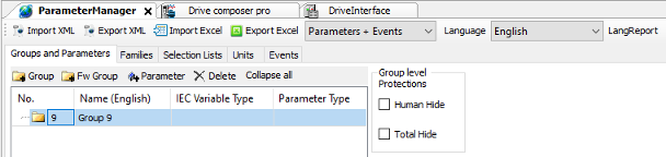
“ParameterManager” automatically selects the first free parameter group number that is not used in the drive firmware or “ParameterManager”.
Importing and exporting parameters
You can import and export “Parameters”, “Events” and “Parameters + Events” in the form of XML format. Choose the desired option from the drop-down list and click “Import XML ”or “Export XML”.
Creating parameters
-
In the “ParameterManager” window, select a parameter group.
-
Click [Parameter] button to create a new parameter. “Parameter Settings” window is displayed.
In the “Parameter Settings” window, you can set the properties of the parameter. The “Parameter Settings” window is identical for all the parameters but there are also custom settings available depending on the parameter type.
-
In the “Parameter Settings” window, enter the “Name” of a parameter and click [Add]. A new parameter is added to the selected group.
Creating parameters
-
In the “ParameterManager” window, select a parameter group.
-
Click [Parameter] button to create a new parameter. Parameter “Settings” window is displayed.
In the “Parameter Settings” window, you can set the properties of the parameter. The “Parameter Settings” window is identical for all the parameters but there are also custom settings available depending on the parameter type.
-
In the “Parameter Settings” window, enter the “Name” of a parameter and click [Add].
A new parameter is added to the selected group.
Parameter settings
In the “Parameter Settings”, you can set parameter properties.
Parameter name
The name shown in the parameter list when using Drive Composer pro or ACS-AP- x control panel.
Parameter type
Defines the type of parameter.
The following parameter types are available in the drop-down list.
-
Decimal number
-
Formatted number
-
Bit pointer
-
Value pointer
-
Plain value list
-
Bit list (16 bit)
IEC variable name
Used to define IEC variable for the parameter.
-
The New option maps the parameter to a new IEC variable. If you do not give a name for the new IEC variable, the parameter name is used as the IEC variable name.
-
When you create a new IEC variable, you must select the variable type, for ex- ample, REAL. The selected parameter type restricts the variable type selection and only the allowed types are shown in the IEC variable/Type list.
-
The Existing option maps the parameter to an already existing IEC variable by finding the parameter from the list of the Input Assistant or writing the name to the field.
Parameter family
Includes a parameter as part of the parameter family and inherits the settings defined for the family.
Function types
These are flag configurations for parameters which determine the parameter behavior with the ACS-AP-x control panel and PC tool displays.
There are five different configurations:
-
Setting (adjustable) - This function type is a generic configuration parameter. When a parameter with this function type is changed by ACS-AP-x control panel or Drive Composer pro, the changed value is saved.
-
Setting (reverts to default) - Used to request a function. When this request is processed, the parameter returns to its default value.
-
Signal (read only) - Displays the application parameter value in the ACS-AP-x control panel or Drive Composer pro. A parameter of this function type does not have any meaningful default value.
-
Signal (resettable) - This function type is identical to the read-only signal and allows to reset parameters to their default values.
-
Custom - Enables to change the values in the application.
Saving types
Define the method of storing the parameter value to the non-volatile memory.
There are three different saving types:
-
No - Does not store the parameter value changes done in the ACS-AP-x control panel or Drive Composer pro.
-
Powerfail - If the parameter 95.04 is set to Internal 24V, the powerfail type parameters are saved immediately at the time of power failure in the drive. If the parameter 95.04 = External 24V, the values are saved at periodic intervals of 1 minute. The powerfail saved parameters are limited to < 10.
-
Immediate - If the parameter value is changed using keypad or PC tool, this type saves the value immediately within 10 seconds. This saving type is used for controls, but not for signals.
Protection, hiding and excluding from
Allows you to set the following protections for parameters or set them on the parameter group level by selecting a parameter group in “ParameterManager”.
backup
-
“Human WP/Human Hide” write protects/hides the parameter from a human user manipulation. This setting can be bypassed using configuration tools, fieldbus controllers, and so on.
-
“Total WP/Total Hide” write protects/hides the parameter from any kind of manipulation outside the firmware. These parameters are used only by the application.
The following settings are for parameters only:
-
“WP Run” protects the parameter from writing when the drive is running.
-
Include in user set includes parameter as a part of the process where all the parameters become a user set.
-
Exclude from Backup leaves the parameter out of parameter backup, but restores the default parameter values. This setting applies only for parameters.
Minimum, Maximum and Default value
These are set for decimal and formatted numbers.
-
“Minimum” and “Maximum” define the limits for the value of the parameter. These values should not exceed the limits of the data type defined for the parameter.
-
Default value is the value of the parameter at the start-up of the program and it must be within the limits defined by the minimum and maximum values. The default value returns if you restore defaults or clear all with parameter 96.06 .
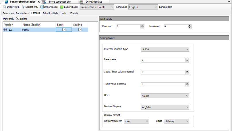
Scaling
Base value is the internal firmware value. The scaling values in Base value, 32-bit scaler and 16-bit scaler must match each other and define how a value of the parameter is represented in other contexts. Scaling the other values of a parameter is calculated based on the defined scaling values.
If the scaling factor is 1, meaning direct transform from one representation to another, use the same number for all of the scaling values
Example
The firmware uses values 0…1 for motor rotation speed measurement. The maximum speed is 1500 rpm, and therefore the ACS-AP-x control panel displays 1500 rpm when the internal value is 1 (the maximum speed). The 16-bit fieldbus device shows 100%.
In this example the values are: Base value = 1, Value (32-bit int) = 1500, Value (16-bit int) = 100
Tool/Fieldbus 32-bit interface
-
32-bit scaler - 32-bit external value (for example, Drive Composer pro or ACS-AP-x control panel)
-
Decimal display - Defines the number of decimal digits displayed on the Drive Composer pro or ACS-AP-x control panel. This setting applies only for an external value, but has no effect on the internal value.
Fieldbus 16-bit interface
-
16-bit interface support - This field defines if the 16-bit external format is allowed, for example, in fieldbus devices and how it is scaled to the 32-bit external format:
-
No - 16-bit external format is not allowed.
-
Direct - 32-bit scaling is used but the value is displayed as a 16-bit value. Therefore, the value (16-bit int) is considered meaningless.
-
Scaled - separate 16-bit scaling is used. Value (16-bit int) must be defined.
-
-
16-bit scaler - 16-bit external value (for example, fieldbus devices).
Testing for scaling
Internal value calculates the scaling of 32 and 16 bit fieldbus interface with the corresponding IEC variable. For description of formula, see PAR_SCALE_CHG function block.
Linking parameter to application code
The IEC variable field in the “Parameter Settings” window enables to link a parameter to an application program code. There are two options to link a parameter with an application program code.
-
The New option adds a new IEC variable to the program and is visible in the input assistant under “ApplicationParametersandEvent” object.
-
The Existing option allows linking a parameter to the existing IEC program variable using browser. Make sure to select the correct data type. If you change the link to the existing IEC variable, a build error occurs. For information on incorrect linked parameters, see the message box. Check the full path to correct the missing linked parameters according to the program.
The existing retain variables cannot be linked to application parameters.
Parameter types
In the “Parameter Settings” window, you can select the “Parameter Type” for the newly created parameter.
-
Decimal number creates a parameter with actual numeric contents, either decimal or non-decimal numbers. The available IEC types are REAL, UDINT, UINT, DINT and INT.
-
Formatted number parameter type is used to make special purpose parameters like date displays, version texts, passcodes, and so on. The available IEC types are UDINT, UINT, DINT and INT. In the Display format for Data Parameter, you can define the format in which the value should be displayed in the Drive composer or ACS-AP-x control panel.
-
Bit pointer creates a pointer parameter which can be assigned to point to a bit of another parameter. You must associate the bit pointer parameter to a selection list (a bit pointer list) that must be created beforehand. The only available IEC type for bit pointer is BOOL. You can define the default selection from the list.
-
Value pointer creates a pointer parameter which can be assigned to point to another parameter. You must associate the value pointer parameter to a selection list (a value pointer list). The only available IEC type for the value pointer is UDINT. You can define the default selection from the list.
-
Plain value list must be associated to a selection list (a plain value list). It allows only values of a list as its own value. The available IEC types are UDINT, UINT, DINT and INT. You can define the default selection from the list.
-
Bit list (16 bit) consists of maximum 16 Boolean values (bits). You can add new rows (bits) to the list using the Bitlist row button. You can change the names of the bits and their values to represent their purpose. The default value is the bit value at the start-up of the program. The only available IEC type is UINT.
Parameter families
If a parameter shares some of its attributes (scaling, minimum/maximum, and so on) with another parameter, it can belong to a family that describes these common attributes. This way, when the attribute is changed in one parameter, it is also changed in all parameters belonging to the same family.
The system library includes a function block to modify parameter attributes like PAR_UNIT_SEL functions. See AY1LB_System_ACS880_V3_5 library in Appendix B: ABB drives system library.
If you select a “Parameter Family” version style, make sure the family has a unique “Name”. The parameter families can define limit or scaling properties or both.
Selection lists
Selection lists are always associated to a parameter of the same type as in the list. They are accessed only through the parameters.
-
In “ParameterManager” window, click “Selection Lists ” tab and then click “Selection list ” to add values.
-
Select the “Type” of selection list and enter the name and then click [Add].
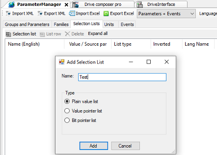
The selection list is created.
-
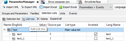
You can add the list row by clicking on “List” row button. If you want to rename the list, double-click on the created list.
You cannot change the type of selection. If you want to change the type of selection, delete and create a new selection list.
-
Name (English) - The text visible to the user. Note that the name is not the official text since the language translator use this text as a source when creating the official language texts.
-
Value/Source par - The value of the list row. For the bit and value pointers, it is the index of the row in the list. For the value lists, it is an actual selectable value.
-
List type - There are three different types of selection lists:
-
Bit pointer list - By default, the bit pointer list has the const_false and const_true values. You can add single bits of any parameter of the appropriate type.
-
Value pointer list - By default, the value pointer list has the const_null value. You can add any parameter which has the same data type as the pointer associated to the list.
-
Plain value list - You can add any values of type INT, DINT, UINT or UDINT. The type should be same as the type of the pointer associated to the list.
-
Inverted - When a bit /value is read from a source parameter, it is inverted /negated for output when the inverted flag is set.
Units
You can create own units for the application parameters. A unit has a unique number and a name. The allowed unit codes for the application program are 128…255.
You can add translations of the name into other languages.
-
In the “ParameterManager” view, click [Units ] tab.
-
Click [New Unit ] to add unit and click [Add ] to add Language Id.
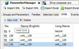
The units are attached to parameters in the “Add Parameter” options in “Parameter Settings” window.
Application events
You can configure your own application events (faults or warnings). The application program then triggers the event and the event registers in the drive event logger with a time stamp. The tool defines the event ID code, type and event name (with translation).
In the “ParameterManager” view, click [Events ] tab and then click [Event ] to add “Event”.
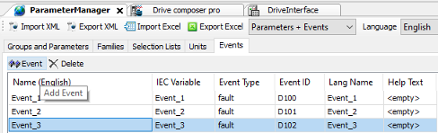
“Events” dialog box gives the following information:
-
Name, in this example “Event_1”. The “Event” name is displayed on the ACS-AP-x control panel and in the Drive composer tools when the event is activated/deactivated.
-
“Event Type”, in this example fault.
The following event types are supported:
-
1 = Fault (Trips the drive)
-
2 = Warning (Is registered to the event logger)
-
3 = Pure event (Is registered to another logger)
-
“Event ID”, in this example D100. Each type of event has its numerical range (ID code). You can select the ID code within the range.
The event is activated by using the EVENT function block in the program code (library AY1LB_System_ACS880_V3_5). Every event must have its own instance of the EVENT block. The EVENT function block must have the same ID code and type as defined in the previous dialog box.