


-
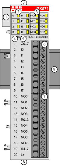
8 digital inputs 24 V DC / 24 V AC (I0 ... I7) in 1 group
-
8 digital normally open relay outputs 24 V DC / 24 V AC or 100 V AC ... 240 V AC, 2 A max. (NO0 ... NO7) in 2 groups
-
Group-wise galvanically isolated
1
I/O bus
2
8 yellow LEDs to display the signal states of the inputs I0 ... I7
3
8 yellow LEDs to display the signal states of the outputs NO0 ... NO7
4
Terminal number
5
Allocation of signal name
6
Terminal block for input signals (9-pin)
7
Terminal block for output signals (11-pin)
8
2 holes for wall-mounting with screws
9
DIN rail
-
Intended purpose
-
Functionality
-
Connections
-
I/O configuration
-
Parameterization
-
Diagnosis
-
State LEDs
-
Technical data
-
Dimensions
-
Ordering data