


-
8 digital inputs 120/230 V AC
-
4 relay outputs with one change-over contacts each
-
Module-wise galvanically isolated
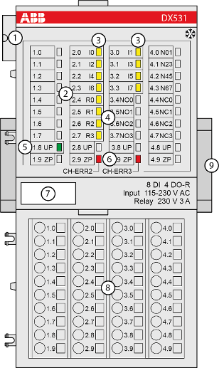
1
I/O bus
2
Allocation between terminal number and signal name
3
8 yellow LEDs to display the signal states at the digital inputs (I0 ... I7)
4
4 yellow LEDs to display the signal states at the digital relay outputs (R0 ... R3)
5
1 green LED to display the state of the process supply voltage UP
6
2 red LEDs to display errors
7
Label
8
Terminal unit
9
DIN rail

Sign for XC version
-
Intended use
-
Connections
-
Internal data exchange
-
Parameterization
-
Diagnosis
-
State LEDs
-
Technical data
-
Dimensions
-
Ordering data