


-
4 analog inputs (resolution 12 bits including sign)
-
2 analog outputs (resolution 12 bits including sign)
-
8 digital inputs 24 V DC
-
8 digital outputs 24 V DC, 0.5 A max
-
Module-wise galvanically isolated
-
Fast counter
-
XC version for use in extreme ambient conditions available
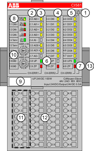
1
I/O bus
2
Allocation between terminal No. and signal name
3
6 yellow LEDs to display the signal states of the analog inputs/outputs (AI0 ... AI3, AO0 ... AO1)
4
8 yellow LEDs to display the signal states of the digital inputs (DI0 ... DI7)
5
8 yellow LEDs to display the signal states of the digital outputs (DO0 ... DO7)
6
2 green LEDs to display the supply voltage UP and UP3
7
3 red LEDs to display errors (CH-ERR1, CH-ERR2, CH-ERR3)
8
5 System LEDs: PWR/RUN, CN-RUN, CN-ERR, S-ERR, I/O-Bus
9
Label
10
2 rotary switches for setting the CANopen Node ID
11
10 terminals to connect the CANopen bus signals
12
Terminal unit
13
DIN rail

Sign for XC version