


|
Parameter |
Value |
|
|---|---|---|
|
Number of channels per module |
8 |
|
|
Distribution of the channels into groups |
1 group of 8 channels |
|
|
Terminals of the channels DC0 ... DC7 |
Terminals 2.0 .... 2.7 |
|
|
Reference potential for all outputs |
Terminals 2.9 ... 4.9 (negative pole of the supply voltage, signal name ZP) |
|
|
Common power supply voltage |
For all outputs terminal 4.8 (positive pole of the supply voltage, signal name UP3) |
|
|
Output voltage for signal 1 |
UP3 (-0.8 V) |
|
|
Output delay (0->1 or 1->0) |
On request |
|
|
Output current |
|
|
|
Rated value per channel |
500 mA at UP3 = 24 V |
|
|
Max. value (all channels together) |
4 A |
|
|
Leakage current with signal 0 |
< 0.5 mA |
|
|
Fuse for UP3 |
10 A fast |
|
|
Demagnetization with inductive DC load |
Via internal varistors (see figure below this table) |
|
|
Output switching frequency |
|
|
|
With resistive load |
On request |
|
|
With inductive loads |
Max. 0.5 Hz |
|
|
With lamp loads |
11 Hz max. at 5 W max. |
|
|
Short-circuit-proof / overload-proof |
Yes |
|
|
Overload message (I > 0.7 A) |
Yes, after ca. 100 ms |
|
|
Output current limitation |
Yes, automatic reactivation after short circuit/overload |
|
|
Resistance to feedback against 24 V signals |
Yes (software-controlled supervision) |
|
|
Max. cable length |
|
|
|
Shielded |
1000 m |
|
|
Unshielded |
600 m |
|
The following drawing shows the circuitry of a digital input/output with the varistors for demagnetization when inductive loads are switched off.
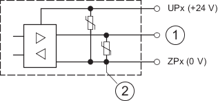
- 1
-
Digital input/output
- 2
-
For demagnetization when inductive loads are turned off