


-
3 serial UART interfaces (RS-232, RS-422 or RS-485)
-
Module-wise galvanically isolated
-
XC version for usage in extreme ambient conditions available
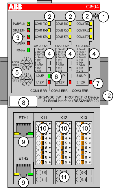
1
I/O bus
2
3 x 3 yellow LEDs to display the signal states of the serial interfaces COM1, COM2 and COM3
3
5 system LEDs: PWR/RUN, STA1 ETH, STA2 ETH, S-ERR, I/O-Bus
4
Allocation between terminal number and signal name of the serial interfaces
5
2 rotary switches for setting the I/O device identifier
6
1 green LED to display the process voltage UP
7
3 red LEDs to display errors (COM1-ERR, COM2-ERR, COM3-ERR) of the serial interfaces
8
Label
9
Ethernet Interfaces (ETH1, ETH2) on the terminal unit
10
3 removable connectors to connect the interfaces
11
6 spring terminals for power supply voltage (UP)
12
DIN rail

Sign for XC version
-
Intended purpose
-
Functionality
-
Connections
-
Assignment of the Ethernet ports
-
Addressing
-
Parameterization
-
Diagnosis
-
State LEDs
-
Technical data
-
Dimensions
-
Ordering data