


For a detailed description of the mounting, disassembly and connection of the module, please refer to the ⮫ installation instructions.
The modules are plugged on an I/O terminal unit.
Properly position the modules and press until they lock in place. The terminal units are mounted on a DIN rail or with 2 screws plus the additional accessory for wall mounting.
⮫ “TA526 - Wall mounting accessory”
The connection of the I/O channels is carried out using the 40 terminals of the I/O terminal unit. I/O modules can be replaced without re-wiring the terminal units.
The terminals 1.8 ... 4.8 and 1.9 ... 4.9 are electrically interconnected within the I/O terminal units and have always the same assignment, independent of the inserted module:
Terminals 1.8 ... 4.8: process voltage UP = +24 V DC
Terminals 1.9 ... 4.9: process voltage ZP = 0 V
The maximum current load capability of the terminals must be taken into account.
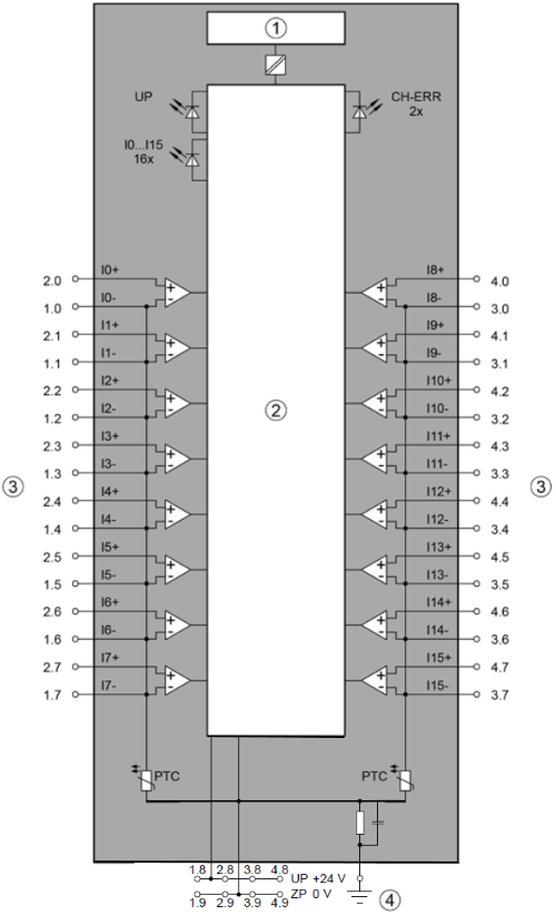
1
I/O bus interface to the CPU or communication interface module
2
Internal logic and I/O circuits of the module
3
Analog outputs
4
Functional earth connection between terminal unit and DIN rail

WARNING
Removal/Insertion under power
Removal or insertion under power is permissible only if all conditions for hot swapping are fullfilled.
⮫ “Replace an I/O module with hot swap”
The devices are not designed for removal or insertion under power when the conditions for hot swap do not apply. Because of unforeseeable consequences, it is not allowed to plug in or unplug devices with the power being ON.
Make sure that all voltage sources (supply and process voltage) are switched off before doing any of the following actions:
-
Connect or disconnect any signal or terminal block.
-
Remove, mount or replace a module.
Disconnecting any powered devices while they are energized in a hazardous location could result in an electric arc, which could create an ignition source resulting in fire or explosion.
Prior to proceeding, make sure that power is disconnected and that the area has been thoroughly checked to ensure that flammable materials or ignitable concentrations are not present.
The devices must not be opened when in operation. The same applies to the network interfaces.
CAUTION
By installing equipotential bonding conductors between the different parts of the system, it must be ensured that the potential difference between ZP and AGND never can exceed 1 V.
CAUTION
The process supply voltage must be included in the grounding concept (e. g. grounding of the negative terminal).
CAUTION
The potential difference between AGND and ZP at the module must not be greater than 1 V, not even in case of long lines.

NOTICE
Risk of damaging the PLC modules!
Overvoltages and short circuits might damage the PLC modules.
-
Make sure that all voltage sources (supply voltage and process supply voltage) are switched off before you begin with operations on the system.
-
Never connect any voltages or signals to reserved terminals (marked with ---). Reserved terminals may carry internal voltages.
Generally, analog signals must be laid in shielded cables. The cable shields must be grounded at both sides of the cables. In order to avoid unacceptable potential differences between different parts of the installation, low resistance equipotential bonding conductors must be laid.
NOTICE
All I/O channels (digital and analog) are protected against reverse polarity, reverse supply, short circuit and temporary overvoltage up to 30 V DC.
By connecting the sensor's negative pole of the output voltage to AGND, the galvanically isolated voltage source of the sensor is referred to ZP.
If AGND does not get connected to ZP, the sensor current flows to ZP via the AGND line. The measuring signal is distorted, as a very small current flows through the voltage line. The total current through the PTC should not exceed 50 mA. This measuring method is therefore only suitable for short lines and small sensor currents. If there are bigger distances, the difference measuring method should be applied.
The negative poles of the analog inputs are connected to each other to form an "Analog Ground" signal for the module.
Because of their common reference potential, analog current inputs cannot be circuited in series, neither within the module nor with channels of other modules.
For the open-circuit detection (wire break), each analog input channel is pulled up to "plus" by a high-resistance resistor. If nothing is connected, the maximum voltage will be read in then.
-
Connection of resistance thermometers in 2-wire configuration
-
Connection of resistance thermometers in 3-wire configuration
-
Connection of active-type analog sensors (Voltage) with galvanically isolated power supply
-
Connection of active-type analog sensors (Current) with galvanically isolated power supply
-
Connection of active-type analog sensors (Voltage) with no galvanically isolated power supply
-
Connection of passive-type analog sensors (Current)
-
Connection of active-type analog sensors (Voltage) to differential inputs
-
Use of analog inputs as digital inputs