


The PROFIBUS state is shown by state LEDs.
|
LED |
Color |
State |
Description |
|
|---|---|---|---|---|
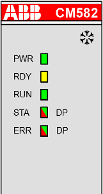 |
PWR |
Green |
ON (light) |
Power supply available. |
|
OFF (dark) |
Power supply not available or defective hardware |
|||
|
RDY |
Yellow |
ON |
Boot procedure |
|
|
Blinking |
Boot failure |
|||
|
OFF |
--- |
|||
|
RUN |
Green |
ON |
Communication module is operational |
|
|
Blinking |
--- |
|||
|
OFF |
Communication module is not operational |
|||
|
STA |
Green |
ON |
Communication to all slaves is established |
|
|
Flashes cyclic |
--- |
|||
|
Flashes non-cyclic |
No configuration or stack error |
|||
|
OFF |
No communication |
|||
|
ERR |
Red |
Blinking |
No data exchange to the master module or the cable is disconnected |
|
|
OFF |
No error |
|||
|
STA |
Yellow |
Blinking (synchronously) |
No production data available, no bus communication possible. |
|
|
ERR |
Yellow |
|||
|
LED state during firmware update |
STA |
Green |
Blinking (synchronously) |
Firmware file transfers during communication module firmware update. |
|
ERR |
Red |
|||
|
STA |
Green |
Blinking (alternately) |
Communication module writes the firmware file to the internal flash. Do not power off the PLC! |
|
|
ERR |
Red |
|||