In the CFC editor, you can wire POUs to each other and create well-structured block diagrams.
The editor supports you in the following ways:
-
Programming with elements and connecting lines
-
Dragging instances and variables to the editing area
-
Auto-routing the connecting lines
-
Automatic linking
-
Fixing of connecting lines by control points
-
Collision detection
-
Input assistance for connection marks
-
Forcing and writing of values in online mode
-
Movement of selection using arrow keys
-
Reduced display of a POU without disconnected pins
Inserting elements and wiring with connecting lines
-
Drag a “Box” element and an “Output” element into the editor.
-
Click the output of the “Box” element.
The output is marked with a red box.
-
Drag a connecting line from the box output of the “Box” element to the box input of the “Output” element.
The cursor symbol changes when it reaches the box input.
-
Release the left mouse button.
The output pin of the box is wired to the input pin of the output.
You can also hold down the [Ctrl] key, select each pin, and then right-click “Connected Selected Pins”.
Calling of instances
-
Create a new project using the standard template and specify the name
Firstfor example.The project
First.projectis created. -
Extend the application with the function block
FB_DOItin the “ST” implementation language with inputs and outputs.FUNCTION_BLOCK FB_DoIt VAR_INPUT iAlfa : INT; iBravo: INT; sCharlie : STRING := 'Charlie'; xItem : BOOL; END_VAR VAR_OUTPUT iResult : INT; sResult : STRING; xResult : BOOL; END_VAR VAR END_VAR iResult := iAlfa + iBravo; IF xItem = TRUE THEN xResult := TRUE; END_IF
-
Select the application and click “Add Object POU” in the context menu. Select the “Continuous Function Chart (CFC)” implementation language and the type
Program. Specify the namePrgFirstfor example.Click “OK” to confirm the dialog.
The program
PrgFirstis created and it opens in the editor. It is still empty. -
Instantiate function blocks and declare variables.
PROGRAM PrgFirst
VAR
	iCounter: INT;

	fbDoIt_1 : FB_DoIt;
	fbDoIt_2 : FB_DoIt;

	iOut : INT;
	sOut: STRING;
	xOut: BOOL;

END_VAR
-
Drag a “Box” element from the “ToolBox” view into the editor.
-
Click the
???field and type inADD.The box type is
ADD. The box acts as an adder. -
Click line 3 in the declaration editor.
The declaration line of
iCounteris selected. -
Click in the selection and drag the selected variable into the implementation. Focus there on an input of the
ADDbox.An input has been created, declared, and connected to the box.
-
Click again in the selection and drag the variable to the output of the
ADDbox.An output has been created, declared, and connected to the box.
-
Drag an “Input” element from the “ToolBox” view to the implementation. Click its
???field and type in1. -
Connect the
1input to an input of theADDbox.A network is programmed. At runtime, the network counts the bus cycles and stores the result in
iCounter.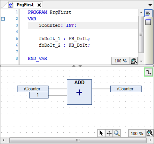
-
Click line 5 in the declaration editor.
The line is selected.
-
Click in the selection and drag the selected instance into the implementation.
The instance appears as a POU in the editor. The type, name, and POU pins are displayed accordingly.
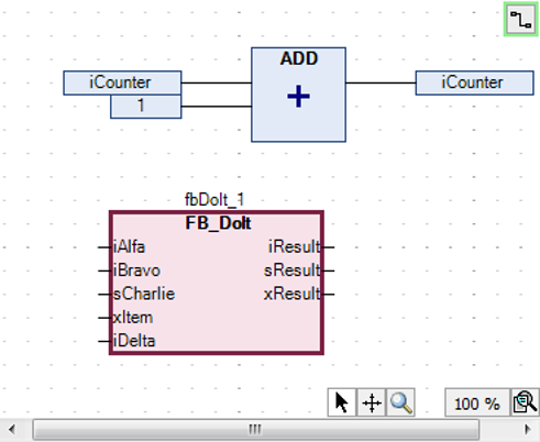
-
Drag the
fbDoIt_2instance to the editor. Interconnect the instances to each other and to inputs and outputs.Example:
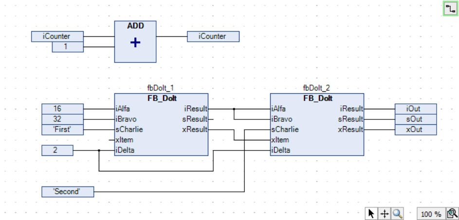
A program in ST with the same functionality might look like this:
PROGRAM PrgFirstInSt
VAR
	iCounter: INT;

	fbDoIt_1 : FB_DoIt;
	fbDoIt_2 : FB_DoIt;

	iOut : INT;
	sOut: STRING;
	xOut: BOOL;

END_VAR
iCounter := iCounter + 1;
fbDoIt_1(iAlfa := 16, iBravo := 32, sCharlie := 'First', xItem := TRUE, iDelta := 2, iResult => fbDoIt_2.iAlfa, xResult => fbDoIt_2.xItem);
fbDoIt_2(iBravo := fbDoIt_1.iResult, sCharlie := 'Second', iDelta := 2, iResult => iOut , sResult=> sOut, xResult => xOut);
Creating connection marks
Requirement: A CFC POU has connected elements.
-
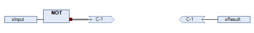
Select a connecting line between two elements.
The connecting line is displayed as selected. The ends of the connecting line are marked with red boxes (
 ).
). -
Click “CFC Connection Mark”.
The connection is separated into a “Connection Mark - Source” and a “Connection Mark - Sink”. The name of the mark is generated automatically.
-
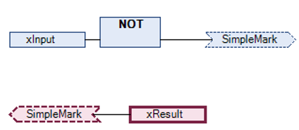
Click in the source connection marks.
You can edit the name.
-
Specify a name
SimpleMarkfor the source connection mark.The source connection mark and sink connection mark have the same name.
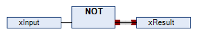
Resolving collisions and fixing connecting lines by means of control points
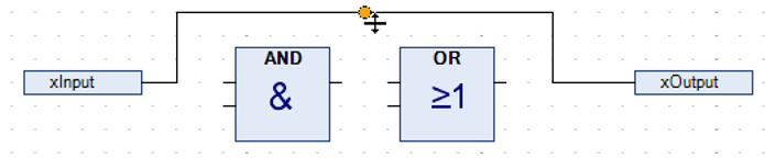
The following example shows how to use the “Route All Connections” command with control points.
-
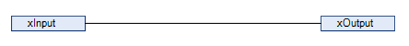
Position the “Input” and “Output” elements. Connect the elements.
-
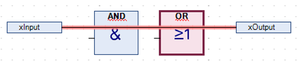
Position two “Box” elements on the line.
The connecting line and the boxes are marked red because of the collision.
-
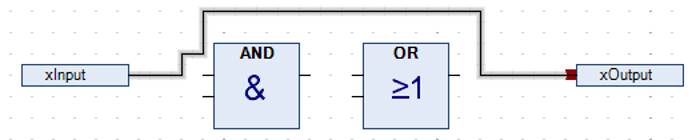
Click “CFC Routing Route All Connections”.
The collision is resolved.
-
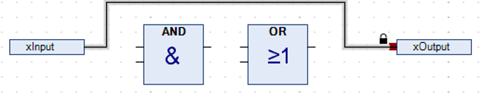
Change the connecting lines gradually.
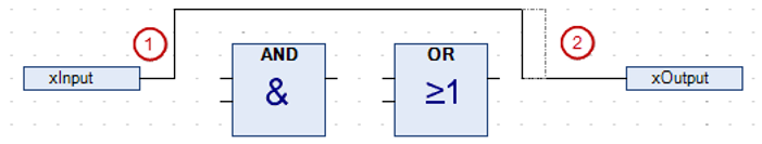
The connecting line has been changed manually and is now blocked for auto-routing. This is shown by a lock symbol at the end of the connection.
-
Select the connecting line and click “CFC Routing Create Control Point”.
A control point is created on the connecting line. The connecting line is fixed to the control point.
You can also drag a control point from the “ToolBox” view to a line.
-
Change the connecting line as seen in the following example.
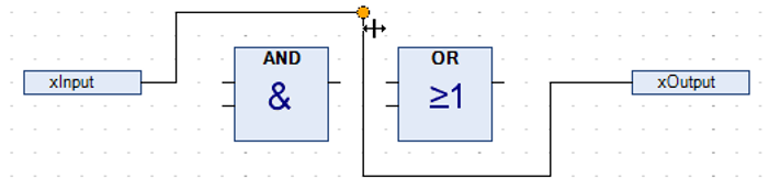
Use the control point for changing the connecting line according to your needs. You can set any number of control points.
-
In the context menu, click “CFC Routing Remove Control Point” to remove the control point.
-
Unlock the connection by clicking “Unlock Connection” or by clicking the lock symbol.
-
Select the connecting line and click “Route All Connections”.
The connecting line is routed automatically as seen in Step 3.

NOTICE
Connections in a group are not auto-routed.
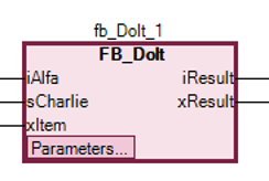
Reducing the display of a POU
Requirement: A CFC POU is open. In the editor, its POUs with all declared pins are displayed.
-
Select a POU whose pins are partially disconnected.
Example:
fb_DoIt_1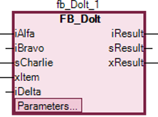
The POU needs space for all of the pins.
-
Click “CFC Pins Remove Unused Pins”.
Now the POU needs less space and is displayed only with the functionally relevant pins.