


CAUTION
If you use pointers to addresses, then the contents of addresses can be moved during an online change. If you use absolute addresses, then the contents of addresses does not change during an online change.
Syntax:
%<memory area prefix> ( <size prefix> )? <memory position>

<memory area prefix> : I | Q | M
<size prefix> : X | B | W | D
<memory position> : <number> ( .<number> )* // Depends on the target system
When defining an address, you use specific character strings to express memory position
and size. An address is marked with the percent sign (%), followed by the memory range prefix, the optional size prefix, and the memory range
position. The numbering that you use for addressing the memory position depends on
the target system.
|
Memory Range Prefix |
|
|---|---|
|
|
Input memory range for "Inputs" For physical inputs via input drivers, "Sensors" |
|
|
Output memory range for "Outputs" For physical outputs via output drivers, "Actuators" |
|
|
Flag memory range |
|
Size Prefix |
Data Type |
Data Width |
|---|---|---|
|
No size prefix |
Single bit |
|
|
|
Single bit |
|
|
|
|
8 bits |
|
|
|
16 bits |
|
|
|
32 bits |
Examples
|
|
Single bit address of the output bit 7.5 |
|
|
Word address of the input word 215 |
|
|
Byte address of the output byte 7 |
|
|
Address of a double word at memory position 48 in flag memory |
|
|
Word address of an input word; interpretation dependent on the current controller configuration |
|
|
Variable declaration with address information of an input word |
|
|
Boolean variable declaration Note: For Boolean variables, one byte is allocated internally if a single bit address
is not specified. A change in the value of |
|
|
Boolean variable declaration with explicit specification of a single bit address. On access, only the input bit 7.5 is read. |
Memory position
Make sure that the address is valid as follows:
To map a valid address in an application, you must know the required position (applicable
memory range) in the process image: input memory range (I), output memory range (Q),
and flag memory range (M) — see above. Furthermore, you have to specify the required
size prefix: bit, BYTE, WORD, DWord (see above: X, B, W, D)
The current device configuration and device settings (hardware structure, device description,
I/O settings) play a decisive part. Note specifically the differences in the interpretation
of bit addresses for devices with "byte addressing mode" and devices with "word-oriented
IEC addressing mode". For example, in a byte addressing device, the number before
the point of bit address %IX5.5 addresses byte 5. On the other hand, in a word-addressed device, it addresses word
5. In contrast, addressing with a word or byte address is independent of the device
type: with %IW5 always word 5 is addressed and with byte address %IB5 always byte 5. Regardless of size and addressing mode, you can address different
memory cells therefore with the same address information.
The following table shows the comparison of byte addressing and word-oriented IEC addressing for bits, bytes, words, and double words. It also shows the overlapping memory ranges that are present in the case of byte addressing (see also the example below the table).
Regarding syntax, note that the IEC addressing mode is always word-oriented. In this case, the word number is located before the point and the bit number ofter the point.
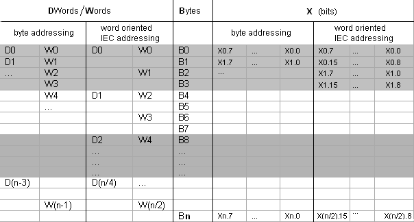
n = byte number
Example of memory range overlapping in the case of the byte addressing mode
D0 contains B0 - B3, W0 contains B0 and B1, W1 contains B1 and B2, and W2 contains B2 and B3. Consequently, in order to avoid overlap, you must not use W1 (also D1, D2, and D3) for addressing.
See also