


Pressure control process flow diagram.
Pressure control is used in applications with individual or multiple water consumers like in water distribution networks. A typical pressure control application diagram is shown below.
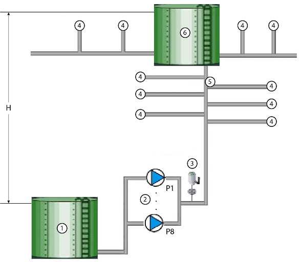
- 1
-
Suction tank
- 2
-
Parallel operating pumps P1 ... P8
- 3
-
Pressure setpoint, discharge pressure
- 4
-
Consumer
- 5
-
Water distribution network
- 6
-
Water tower buffer tank
- H
-
Water head between the levels in the suction tank and water tower buffer tank
Using pressure control
Pressure control in the pumping library can help in the following operations:
-
Water consumption fluctuates always and may be discontinuous over a time period, because of which it is difficult to have a continuous flow rate like in the flow control process.
-
The number of pumps and the pump speed is decided by the water consumption in the water distribution system.
-
Water is supplied to the pump station through suction pipeline from a suction tank.
-
The pumps may be operating in parallel.
-
The discharge pressure is measured in the discharge pipeline. The measured discharge pressure is controlled according to the pressure set point.
-
Each pump must be started with a minimum speed to build up the pressure which is required to produce a minimum flow.
-
The pressure to deliver a minimum flow depends of the water head (H) between the water levels in the suction tank and target tank.
-
If there is pump station shutdown due to protection shutdown input, the pumps must be stopped sequentially to prevent water hammering.
Variable speed drives should be stopped through a speed ramp. Otherwise, the water hammering will quickly wear out the pipeline connections and the pump station equipment.
Pump combinations for pressure control
Pressure control mode works for two types of pump combinations: Multi pump and traditional pump.
The combination of function blocks to execute a pressure control is shown in the figures below.
-
Multi pump – In this mode all pumps are run using VFDs.
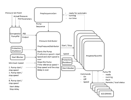
Traditional pump – In this mode only one pump will run using the VFD and the rest of the pumps will run using the direct-on-line motors. The pump, which is fed by VFD will always be master or lead pump.
Based on the load requirement the number of pumps operating can change but the pump fed by VFD will always be operating.
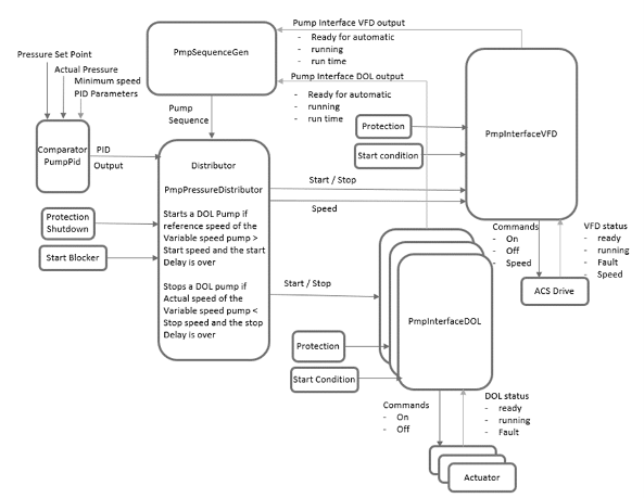
The pressure control mode cannot be supported by a DOL pump.
The combination with any VFD pump is necessary.