


For a detailed description of the mounting, disassembly and connection of the module, please refer to the ⮫ installation instructions.
The connection is carried out by using the 40 terminals of the terminal unit TU515/TU516.
The assignment of the terminals:
|
Terminal |
Signal |
Description |
|---|---|---|
|
1.0 |
DO0 |
Signal of the digital output DO0 |
|
1.1 |
DO1 |
Signal of the digital output DO1 |
|
1.2 |
DO2 |
Signal of the digital output DO2 |
|
1.3 |
DO3 |
Signal of the digital output DO3 |
|
1.4 |
DO4 |
Signal of the digital output DO4 |
|
1.5 |
DO5 |
Signal of the digital output DO5 |
|
1.6 |
DO6 |
Signal of the digital output DO6 |
|
1.7 |
DO7 |
Signal of the digital output DO7 |
|
1.8 |
UP |
Process voltage UP (24 V DC) |
|
1.9 |
ZP |
Process voltage ZP (0 V DC) |
|
2.0 |
DO8 |
Signal of the digital output DO8 |
|
2.1 |
DO9 |
Signal of the digital output DO9 |
|
2.2 |
DO10 |
Signal of the digital output DO10 |
|
2.3 |
DO11 |
Signal of the digital output DO11 |
|
2.4 |
DO12 |
Signal of the digital output DO12 |
|
2.5 |
DO13 |
Signal of the digital output DO13 |
|
2.6 |
DO14 |
Signal of the digital output DO14 |
|
2.7 |
DO15 |
Signal of the digital output DO15 |
|
2.8 |
UP |
Process voltage UP (24 V DC) |
|
2.9 |
ZP |
Process voltage ZP (0 V DC) |
|
3.0 |
AI0+ |
Positive pole of analog input signal 0 |
|
3.1 |
AI1+ |
Positive pole of analog input signal 1 |
|
3.2 |
AI2+ |
Positive pole of analog input signal 2 |
|
3.3 |
AI3+ |
Positive pole of analog input signal 3 |
|
3.4 |
AI- |
Negative pole of analog input signals 0 ... 3 |
|
3.5 |
AO0+ |
Positive pole of analog output signal 0 |
|
3.6 |
AO1+ |
Positive pole of analog output signal 1 |
|
3.7 |
AO- |
Negative pole of analog output signals 0 and 1 |
|
3.8 |
UP |
Process voltage UP (24 V DC) |
|
3.9 |
ZP |
Process voltage ZP (0 V DC) |
|
4.0 |
DC16 |
Signal of the configurable digital input/output DC16 |
|
4.1 |
DC17 |
Signal of the configurable digital input/output DC17 |
|
4.2 |
DC18 |
Signal of the configurable digital input/output DC18 |
|
4.3 |
DC19 |
Signal of the configurable digital input/output DC19 |
|
4.4 |
DC20 |
Signal of the configurable digital input/output DC20 |
|
4.5 |
DC21 |
Signal of the configurable digital input/output DC21 |
|
4.6 |
DC22 |
Signal of the configurable digital input/output DC22 |
|
4.7 |
DC23 |
Signal of the configurable digital input/output DC23 |
|
4.8 |
UP |
Process voltage UP (24 V DC) |
|
4.9 |
ZP |
Process voltage ZP (0 V DC) |
The internal power supply voltage for the module's circuitry is carried out via the I/O bus (provided by a communication interface module or a CPU). Thus, the current consumption from 24 V DC power supply at the terminals L+/UP and M/ZP of the CPU/communication interface module increases by 2 mA per DA502.
The external power supply connection is carried out via the UP (+24 V DC) and the ZP (0 V DC) terminals.

WARNING
Removal/Insertion under power
Removal or insertion under power is permissible only if all conditions for hot swapping are fullfilled.
⮫ “Replace an I/O module with hot swap”
The devices are not designed for removal or insertion under power when the conditions for hot swap do not apply. Because of unforeseeable consequences, it is not allowed to plug in or unplug devices with the power being ON.
Make sure that all voltage sources (supply and process voltage) are switched off before doing any of the following actions:
-
Connect or disconnect any signal or terminal block.
-
Remove, mount or replace a module.
Disconnecting any powered devices while they are energized in a hazardous location could result in an electric arc, which could create an ignition source resulting in fire or explosion.
Prior to proceeding, make sure that power is been disconnected and that the area has been thoroughly checked to ensure that flammable materials are not present.
The devices must not be opened when in operation. The same applies to the network interfaces.

NOTICE
Risk of damaging the PLC modules!
Overvoltages and short circuits might damage the PLC modules.
-
Make sure that all voltage sources (supply voltage and process supply voltage) are switched off before you begin with operations on the system.
-
Never connect any voltages or signals to reserved terminals (marked with ---). Reserved terminals may carry internal voltages.
NOTICE
Risk of damaging the PLC modules!
The PLC modules must not be removed while the plant is connected to a power supply.
Make sure that all voltage sources (supply and process voltage) are switched off before you do the following:
-
Connect or disconnect any signal or terminal block.
-
Remove or replace a module.
CAUTION
Risk of imprecise and faulty measurements!
Analog signals may be distorted seriously by external electromagnetic influences.
Use shielded wires when wiring analog signal sources. The cable shield must be grounded at both ends of the cable. Provide a potential equalization of a low resistance to avoid high potential differences between different parts of the plant.
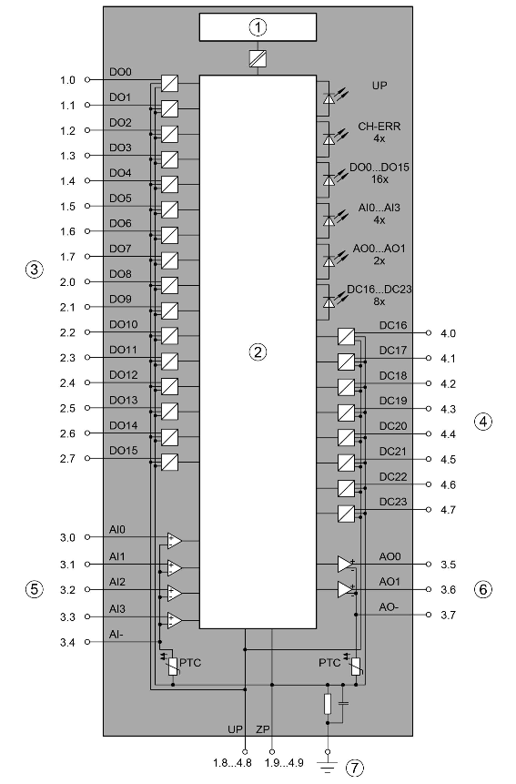
- 1
-
I/O bus interface
- 2
-
Logic
- 3
-
Digital output
- 4
-
Digital input/output
- 5
-
Pole of analog input signal
- 6
-
Pole of analog output signal
- 7
-
Functional earth connection
The module provides several diagnosis functions⮫ “Diagnosis”.
-
Connection of the digital outputs
-
Connection of the configurable digital inputs/outputs
-
Connection of resistance thermometers in 2-wire configuration to the analog inputs
-
Connection of resistance thermometers in 3-wire configuration to the analog inputs
-
Connection of active-type analog sensors (Voltage) with galvanically isolated power supply to the analog inputs
-
Connection of active-type analog sensors (Current) with galvanically isolated power supply to the analog inputs
-
Connection of active-type analog sensors (Voltage) with no galvanically isolated power supply to the analog inputs
-
Connection of passive-type analog sensors (Current) to the analog inputs
-
Connection of active-type analog sensors (Voltage) to differential analog inputs
-
Use of analog inputs as digital inputs
-
Connection of analog output loads (Voltage)
-
Connection of analog output loads (Current)