


With PS5611-Motion different motion control system structures are possible. Independent of the system structure a typical motion control application consists of the following system elements:
-
An application program which contains PLCopen function blocks that defines the general application behavior and logics.
-
A profile generator which generates a position profile based on the dynamic specifications of the application program to guide the axis to the desired positions.
-
A position control loop which outputs a speed reference signal to minimize the following error.
To achieve the best system structure for an application these components can be separated into different devices. Each type of structure has its own kind of interface and type of signals which need to be transferred between the interacting devices.
All shown motion control system structures (Central Motion control with or without position control loop) can be combined together in the same application program for a motion control project.
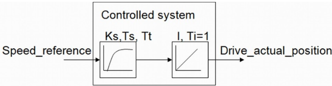
With the function blocks of motion library a motion control profiler can be used inside the PLC. As shown in the following figure it is needed to provide the actual position of the drive. The output can be either a position or a velocity reference signal. The used output signal will then be used to move the axis in the desired way.
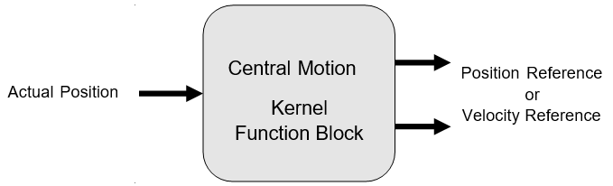
There are 2 possibilities to send a reference value to the drive:
-
When the position control loop is closed by the PLC by a CMC_Basic_Kernel function block, the output Speed_Reference should be connected to the drive. The value of Speed_Reference can be scaled with the axis parameters Max_Rpm and Ref_Max.
-
When the position control loop is closed by the drive, the output Position_Reference should be connected to the drive. The unit for the output Position_Reference is incremented as well as the input Drive_ActualPosition.
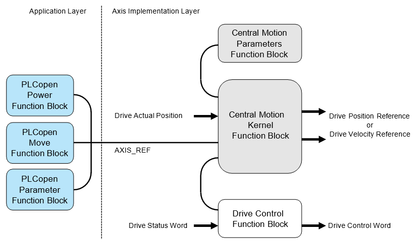
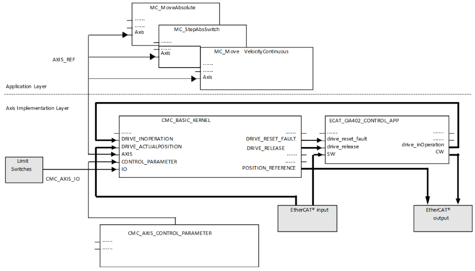
In general the programming of a machine consists of two layers as shown in the figure above.
In the application layer function blocks according to PLCopen motion control are used to program the application sequences with all necessary types of movements and administrational commands. Due to the standard PLCopen motion control this can be reused in any other machine programs that used PLCopen function blocks.
The axis implementation layer is responsible for the execution of the commands from the application layer and can be programmed for each axis in a different way depending on the used hardware components.
|
Library |
Content |
|---|---|
|
ABB_MotionControl_AC500.library |
Kernel function block, Parameters function block, Axis simulation function block |
|
Data types for AC500 motion control |
|
|
Motion control function blocks according to PLCopen |
For a central motion axis implementation the use of the function blocks CMC_Basic_Kernel and CMC_Axis_Control_Parameter are mandatory.
The library design is independent from any bus architecture or any specific drive features.
Example for a possible system architecture
|
System |
Velocity reference |
Position feedback |
|---|---|---|
|
System A |
Output via analog output channel as voltage or current |
From incremental encoder connected to CD522 I/O module |
|
System B |
Output via EtherCAT network |
Input via EtherCAT network |
|
System C |
Output as frequency signal of CD522 I/O module |
From incremental encoder connected to CD522 I/O module |
|
System D |
Output via PROFINET IO network |
Input via PROFINET IO network |
|
System E |
Output via PTO & PWM channel in AC500-eCo |
Input via either encoder (included in onboard IO), or the PTO or PWM pulse count. |
In case the velocity reference value is used from the kernel function block the position control loop is closed inside the drive. In this case, it is necessary to adjust the related parameters from the parameters function block. When the position reference will be used the position control loop is closed inside the drive. In this case, the internal control loop is just used to monitor the position and velocity.
When the position reference is used for the drive the following aspects have to be taken care of:
-
It is necessary to use a real time fieldbus, like EtherCAT.
-
The PLC cycle has to be synchronized to the fieldbus cycle.
-
The task calculation times may not exceed the used cycle time.
The kernel function block
The drive’s status should be managed by a specialized function block that supports the used type of drive as shown in the figure above. The kernel function block is the main function block which is needed to operate an axis with PLC-based motion control. It must be used with the parameter function block which is the interface to input parameters which are used to setup the axis.
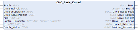
The drive has to be accessed outside the CMC_Basic_Kernel function block. Actual values and reference values might be transferred by a synchronized fieldbus or by I/Os. The function block CMC_Basic_Kernel has to be called every cycle and at least once before any function block MC or MCA is activated.
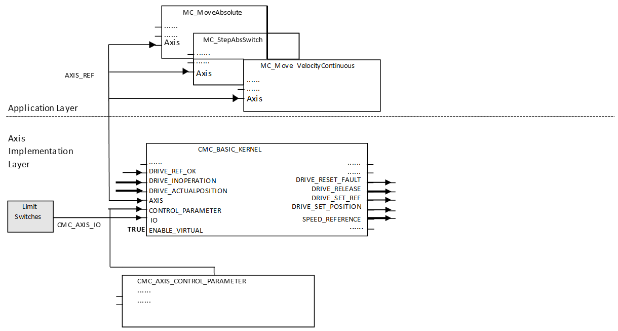
The following figure shows an example with a CiA402 drive on an EtherCAT network. The main data signals are drawn in bold lines. Here, the drive will receive a position reference signal which means that the position control loop is closed inside the drive.
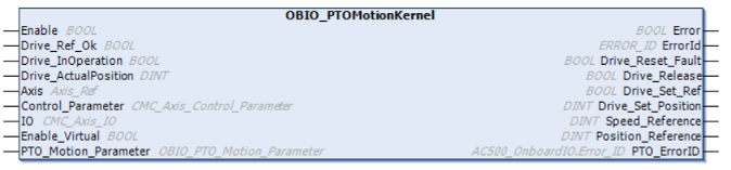
The KERNEL function blocks are available in two variants.
The OBIO_PTOMotionKernel / OBIO_PWMMotionKernel function blocks are solely to be used in eCo V3 CPUs and to make use of the integrated stepper-IO. It connects automatically to the internal IOs. Use the PTO or PWM specific kernel block based on your configuration.
The CMC_Basic_Kernel block is designed to be used in any V3 PLCs and can either work with drives connected to a fieldbus or IO’s.
The below table shows which Kernel is compatible with which PLC and which library they can be found in:
|
Topic |
OBIO_PTOMotionKernel/ OBIO_PWMMotionKernel |
CMC_Basic_Kernel |
|---|---|---|
|
Library |
ABB_MotionControlEco_AC500.library |
ABB_MotionControl_AC500.library |
|
Recommended PLC |
AC500-eCo V3 PLC |
All AC500 V3 PLC’s |
Axis parameters
The parameters for axis configuration and adjustment are set by the function blocks CMC_Axis_Control_Parameter.
Depending on the version of the kernel function block the corresponding version of the parameters function block must be used. The instance will then be connected to the kernel function block by its instance name.
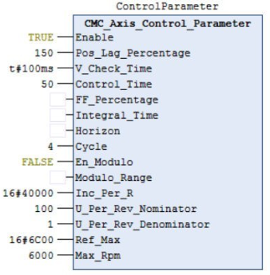
In this example the control structure is a simple position control loop with just proportional gain. When the application does not require minimized position following error it should be used this way as it is simple to adjust, robust and requires minimal performance. The proportional gain is then adjusted by Control_Time. Just change values at CMC_Axis_Control_Parameter when the position control loop is open (Drive_Release=FALSE, the axis state is disabled). The values are sending to the control loop with a positive edge at “Enable”. The CMC_Basic_Kernel function block needs to be already enabled.
Supervision
Pos_Lag_Percentage
This parameter configures the position window for the supervision of the following error. The default value is 150[%]. A value of 0[%] will deactivate the supervision function.
The size of the position window depends on the setting of the parameters Control_Time and Max_Rpm “Control_Time”.
Position Window [Increments] = (Inc_Per_R) * (Max_Rpm/60) * (Control_Time/1000)
Position Window [Units] = (U_Per_Rev_Nominator/ U_Per_Rev_Denominator) * (Max_Rpm/60) * (Control_Time/1000)
Example
Position Window [Increments] = (10000) * (6000/60) * (50/1000) = 50000 [Increments]
Position Window [Units] = (1/1) * (6000/60) * (50/1000) = 5 [Units]
A value of 100% will result in a position window which corresponds to the expected following error with the giving Control_Time at Max_Rpm. Therefore it is recommended to use values higher than 100[%]. In case the parameter FF_Percentage is used smaller values can be used.
If the supervised position window is exceeded the axis state will change to “ERRORSTOP”.
V_Check_Time
After the configured time, the drive’s actual velocity must be at least 50 % of the commanded velocity. This function can also be used in case the position reference is transferred to the drive.
A value of 0 will deactivate this supervision function.
If the supervised velocity window is exceeded the axis state will change to “ERRORSTOP”.
Position control loop
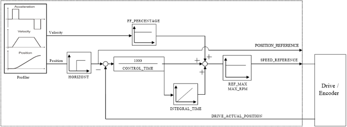
Control_Time
The default value is 100 which leads to a proportional gain of 10.
In case the value of Control_Time is too short the position control loop will run into instability. In case the position control loop has not used this parameter must not be set to 0.
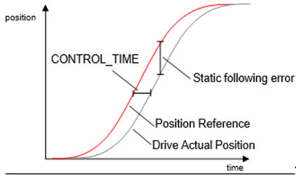
Control_Time and static following error in case the feed forward of velocity and the integrational part of the position control loop is not used.
The static following error depends on the axis velocity and can be calculated easily: Control_Time multiplied by the axis velocity ( p_error = v * CT ).
In general it should be aimed to reach a high position control loop gain with a short Control_Time to achieve a small following error. As the reaction times take account in the possible Control_Time of the complete system (parameters of the drive control loop, PLC cycle time as well as the communication fieldbus) should be considered.
As a basic rule the Control_Time should be at least four times longer than the reaction time between the output of the Speed_Reference and the input of actual position.
When the time Ts and Tt is measured, a Control_Time of 4 * (Ts + Tt) will result in an aperiodic damping of the position control loop. It is important to measure the values from inside the PLC (e.g. Trace) to have the complete reaction times included. Practical values for Control_Time might be from 50 - 500ms. The PLC cycle time as well as bus cycle times and mechanical reaction will influence the value.
FF_Percentage
The default value is 0.
In case a velocity feedforward must be configured a value of up to 80 is recommended. For larger values than 80 the parameter Horizon needs to be used as the resulted position will overshoot otherwise.
A value of 100 adds a velocity to the Speed Reference output which corresponds exactly to the ongoing Position Reference value.
The setting here will effect the position profile based on the projected velocity profile.
Integral_Part
The Integral_Part of the position control loop can be used to eliminate a permanent positioning error, e.g. in case of hanging loads.
The time value can be regarded as the time the integrator needs to sum up the input value to reach the same value for its output.
In case the Integral_Part time is too short the position control loop will run into instability.
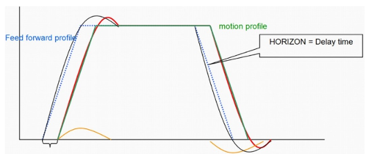
Horizon
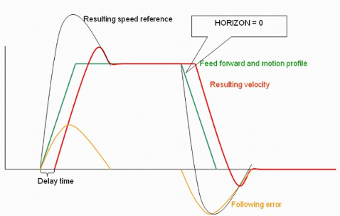
A communication delay of the Speed_Reference value to the drive system can cause an overshoot during positioning caused by the velocity feedforward gain.
This function will compensate this communication delay to prevent an overshoot by time shifting the signals Velocity Feed Forward and Position Reference relatively to each other.
The value of Horizon can be assumed to be approximatley the time delay of the communication delay.
The delay time might be caused by the cycle time of the control loop and by any delay in sending the speed reference, delay in the drive to build up the torque and delay to receive the actual position. To overcome this delay, a Horizon > 0 might be used. The feed forward reference will be created in advance, while the proportional gain is applied to the original motion profile. The delay is then compensated.
This function should not be used if the feed forward parameter FF_Percentage is 0. A value of 0 will deactivate this function, which is the default value.
While this function is used, it will increase the needed PLC calculation time for this axis.
PLC cycle time
This parameter represents the cycle time in which the kernel function block of the axis is called. If the configured cycle time is not correct the resulting acceleration and speed of an axis will be not correct also.
In case the task execution of the axis is synchronized to a fieldbus (e.g. EtherCAT) the cycle time of the fieldbus has to be used
Roll-Over axis
If the Position_Reference value is used, the drive must able to perform a position over-run after 32 bit. If the drive’s position over-run is different, it can be adapted with the function blocks CMC_Binary2Modulo and CMC_Modulo2Binary from the library ABB_MotionControl_AC500.library.
Incompatibility can cause an axis to trip after hours of operation.
The possible position following error must be smaller the ½ Modulo_Range. Make sure that the modulo range is large enough. Position following error = (100 - FF_Percentage) * Max_Rpm * Inc_Per_R * Control_Time/ 6000000. This is the maximum value at constant velocity.
En_Modulo
With this parameter the axis can be configured as a roll-over axis.
Modulo_Range
The modulo range will be defined in drive position counts (DINT). It will result that the scaled unit position which is used by the PLCopen function blocks will stay within the defined range.
When used with CMC_Basic_Kernel64, user can use the modulo range as “0” and En_modulo = true to have the modulo range automatically set as 2^39 and the position range can be both in positive and negative direction.
Example
En_Modulo := TRUE
Modulo_Range := 20000
Inc_Per_Rev := 10000
U_Per_Rev_Nominator := 360 (example – degree)
U_Per_Rev_Denominator := 1
The scaled unit's position will cover the range from 0 to 720 (degrees)
In some cases it is not suitable to set the modulo range of an application with the DINT value of the parameter Modulo_Range only. In such cases the parameters 2001 Modulo_Nominator and 2002 Modulo_Denominator can be used to scale the parameter Modulo_Range to a more precise value.
Parameter Modulo_Nominator and Modulo_Denominator (supported with CMC_Basic_Kernel)
These parameters can be used to modify the Modulo_Range in a way that fractions of an increment could be used for 1 modulo (=rollover) distance
-
Default: Modulo_Nominator=1 and Modulo_Denominator=1: the actual position for an axis is limited between 0 and Modulo_Range increments.
-
Limitations: Modulo_Range*Modulo_Nominator < 2147483647. Otherwise: default values will be used.
-
When modifying these parameters, the position control loop should be opened.
Example 1
En_Modulo = TRUE
Modulo_Range = 1024
Modulo_Nominator = 10
Modulo_Denominator = 3
Inc_Per_R = 1024
U_Per_Rev_Nominator = 80*5*3
U_Per_Rev_Denominator = 10
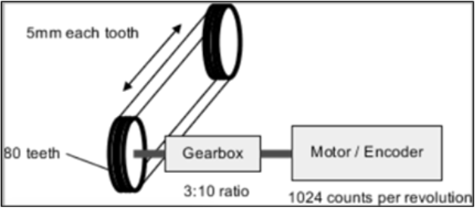
Result of parameters Modulo_Range, Modulo_Nominator and Modulo_Denominator: The modulo range will cover one revolution of the toothed belt wheel.
Result of parameters U_Per_Rev_Nominator and U_Per_Rev_Denominator: One scaled unit corresponds to one mm of the tooth belt.
Example 2
|
Gearbox 10.1 |
Option1 |
Option2 |
|---|---|---|
|
En_Modulo |
TRUE |
TRUE |
|
Modulo_Range |
10240 |
10240 |
|
Modulo_Nominator |
10 |
1 |
|
Modulo_Denominator |
1 |
1 |
|
Inc_Per_R |
1024 |
10240 |
|
U_Per_Rev_Nominator |
36 |
360 |
|
U_Per_Rev_Denominator |
1 |
1 |
|
Max_Rpm |
3000 |
300 |
The two options above describe exactly the same configuration. The Modulo_Range is equivalent to 10 motor revolutions and is 10240 increments. For the position, 1u means 1° and the resolution is 360°/10240inc = 0,035°/Inc = 1°/28,44 Inc.
Example 3
|
Gearbox 10.3 |
Option1 |
Option2 |
|---|---|---|
|
En_Modulo |
TRUE |
TRUE |
|
Modulo_Range |
1024 |
10240 |
|
Modulo_Nominator |
10 |
1 |
|
Modulo_Denominator |
3 |
3 |
|
Inc_Per_R |
1024 |
10240 |
|
U_Per_Rev_Nominator |
108 |
1080 |
|
U_Per_Rev_Denominator |
1 |
1 |
|
Max_Rpm |
3000 |
300 |
The two options above describe exactly the same configuration. The gearbox is 10:3, so the Modulo_Range is equivalent to 1024*10/3 = 3413 + 1/3 increments. For the first option, the resulting modulo range is calculated 1024*10/3, for option2, it is 10240*1/3. For the position, 1u means 1° and the resolution is 108°/1024inc = 0,105°/Inc = 1°/9.481 Inc.
Scaling of the unit of length
Inc_Per_R
With this parameter the number of the drive position counts each revolution of the motor (DINT) have to be entered.
U_Per_Rev_Denominator & U_Per_Rev_Nominator
With these two parameters the number of units which correspond to one revolution of the motor have to be entered.
The units of length can be scaled to values like: mm, inch, degree, …
All dynamic parameters of the PLCopen function blocks like velocity, acceleration and jerk are based on seconds. Velocity [units/s], acceleration [units/s²], jerk [units/s³]
Example 1
Inc_Per_Rev = 10000
U_Per_Rev_Nominator = 360
U_Per_Rev_Denominator = 1
This will scale one unit to one degrees of the motor shaft. Correspondingly a velocity [units/s] of 360 will turn the motor shaft one revolution per second.
Example 2
In the example one unit will be scaled to one millimeter of the conveyor.
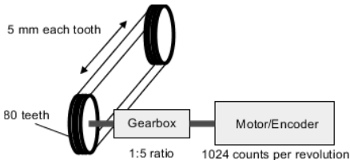
How many units will pass after one revolution of the motor? (80*5 mm) / 5 = 80
Inc_Per_Rev = 1024
U_Per_Rev_Nominator = 80
U_Per_Rev_Denominator = 1
Example 3
In the example one unit will be scaled to one millimeter of the conveyor.
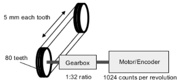
How many units will pass after one revolution of motor? (80*5 mm) / 32 = 12,5 = 125/10
Inc_Per_Rev = 1024
U_Per_Rev_Nominator = 125
U_Per_Rev_Denominator = 10
Scaling of the speed reference output
These two parameters are used to scale Speed_Reference output of the kernel function block in order to reach the intended velocity by the output value and to limit the highest possible output value.
Ref_Max
Highest possible output value of the Speed_Reference output. The Speed_Reference value that corresponds to the parameter Max_Rpm should be used.
Max_Rpm
Maximum speed of the motor in revolutions per minute.
Example
Analog Drive: 1000 rpm at 2 Volts, 3200 rpm at 6,4 Volts (max.)
Analog output module: 10 Volts output at digital value 27648
Ref_Max = 17695 (= 27648 / 10 * 6,4)
Max_Rpm = 3200
Access and modify parameters
All modifications will be effective immediately. There is no extra plausibility check and values are not checked for limitations.
Some parameters are collected inside a structure “Axis_Ref” and can be accessed and modified immediately. They are the same parameters as used with function blocks MC_WriteParameter and MC_ReadParameter.
The differences are:
-
Only available with CMC_Basic_Kernel
-
The parameter values are LREAL instead of DINT and can be used with decimals.
-
The parameters will be effective immediately.
-
There is no check for consistency or limits.
-
The parameters for position control can be checked and modified by accessing the structure parameter.position_control in addition.
|
Parameter |
Description |
|---|---|
|
KP |
Proportional gain in positive direction. Used directly to multiply the following error and create the Reference_Prop. |
|
KF |
Feed forward in positive direction. Used directly to multiply the speed reference and create the Reference_FF. |
|
KP_BACK |
Proportional gain in negative direction. Used directly to multiply the following error and create the Reference_Prop. |
|
KF_BACK |
Feed forward in negative direction. Used directly to multiply the speed reference and create the Reference_FF. |
|
TI |
Integration time. When parameter is used the position control loop has an additional integral part. In TI cycle, the Refer- ence_ITG will reach the value of Reference_Prop, when KI=100*KP. |
|
KI |
Proportional gain, used for integral part of position control loop. |
|
KF_100 |
Value for feed forward gain, if 100% would be used. |
|
Max_Time |
Delay time used for supervision of velocity. With Max_Time=0, no supervision is executed. |
|
D_XS_Max |
Maximum possible velocity in [u/cycle]. The maximum allowed following error is part of the parameter structure, PLCopen parameter paraMaxPositionLag. |
|
Ref_Max |
Limit for Speed_Reference. |
Elements of Axis_Ref
The Axis_Ref structure gives the user not only access to control an axis but also also contains many elements which can be useful to the user.
|
Value |
Description / Contents |
|
|---|---|---|
|
Actual |
Actual Values showing the currently used settings for the axis |
|
|
actual |
Some actual values like positions and velocity per cycle |
|
|
POSITION |
Actual position [u] |
|
|
CONTROL_POSITION |
Used control position [u], could be limited by software limit switch or velocity |
|
|
D_XS |
Actual reference velocity [u/cycle] |
|
|
DD_XS |
Actual acceleration/deceleration (without superimposed movement) |
|
|
D_XI |
Actual velocity [u/cycle] |
|
|
D_XSS |
Actual following error [u] |
|
|
ACT_POS_GAP |
Actual position gap, caused by velocity limitation |
|
|
REFERENCE_PROP |
Proportional part for speed reference, calculated from D_XSS |
|
|
REFERENCE_FF |
Feed forward for speed reference, calculated from D_XS |
|
|
REFERENCE_ITG |
Integral part for speed reference, calculated from D_XSS |
|
|
Expert |
An expert level tunnel for parameter settings to be passed through the axis ref and the generated code |
|
Limitation for velocity, acceleration, and deceleration
From library version 3.1 on, these values are not limited to the 16-bit value range (32767). The limit for velocity is calculated by the values given at CMC_Axis_Control_Parameter and the acceleration is limited such that this velocity cannot be reached faster than 1 cycle.