NOTICE
PLC damage due to missing grounding
-
Make sure to ground the devices.
-
The grounding (switch cabinet grounding) is supplied both by the mains connection (or 24 V supply voltage) and via the DIN rail. The DIN rail must be connected to ground before power is supplied to the device. The grounding may be removed only if it is certain that no more power is being supplied to the control system.
-
In case of screw mounting, use metal screws for grounding.
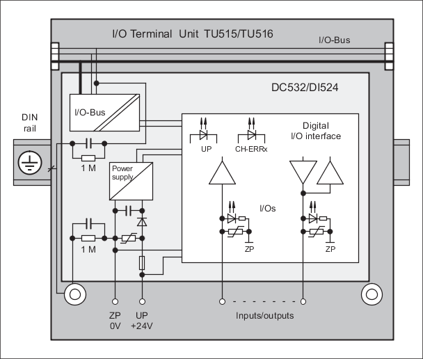
Block diagram: Digital I/O modules
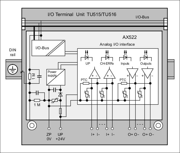
Block diagram: Analog I/O modules