Each PLC contains at least three main tasks/ programs:
-
HA program
-
Application program
-
Modbus program
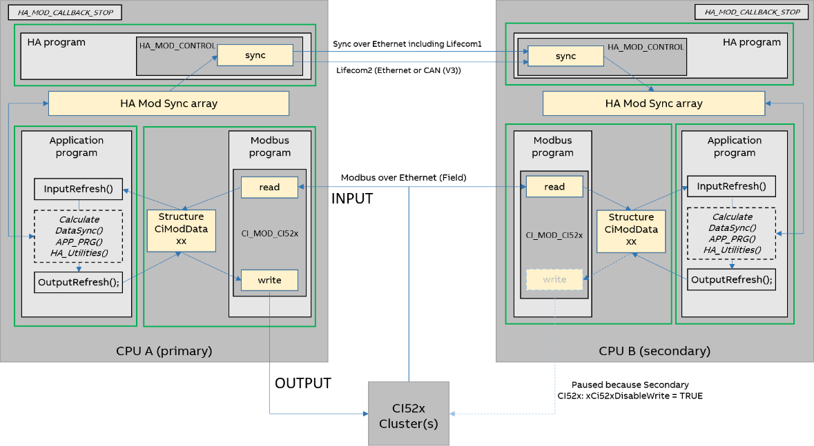
The programs in one PLC communicate via internal structures of the libraries and dedicated internal memory areas for HA-Sync array and the Modbus CI52x memory(ies) CiModDataxx.
|
Layout element |
Meaning |
|---|---|
|
Dotted outline box |
Indicates optional function block or programs. |
|
Solid outline box |
Indicates the mandatory function blocks or programs. All mandatory blocks are called when an export is created from Bulk data manager. |
|
Italic font |
Indicates the program or functions user should call in his project and not created by Bulk data manager. |
|
Light yellow background block / blue arrow |
Indicates the operations which are handled internally in the library. |
|
Green solid box |
Indicates the three different tasks which user has to configure. |
Modbus program
The function block CIModCI52x (V3) / CI_MOD_CI52x (V2) reads the input values from the CI52x modules and stores them in the structure CiModDataxx. If the CPU is primary it also writes the outputs to the CI52x modules. The Function block also parametrizes the CI Module as configured in e.g. Bulk data manager tool during the first startup or when a CI module is exchanged.
Normally the HA-Modbus TCP library takes care of communication monitoring. Nevertheless if com- munication is cut completely, the CI52x communication interfaces and its I/O modules have to react on their own to achieve a bumpless or desired behavior: The following parameters for the CI52x com- munication interfaces and I/O modules need to be considered:
-
– CI52x: parameter “Timeout" for Bus supervision: 2)
Allows to detect errors from communication interface side as well and take action to ensure a fail- safe behavior if communication is cut. It can be set in 10 ms steps. If set to 0 no bus supervision is active. Proposed value: 50 = 500 ms = default in Bulk data manager; this value should be increased, e.g. to value 65 if AC500 CPU ports are used for field communication to take care of the larger TCP retransmit time.
-
“Behaviour Outputs” at “Timeout for Bus supervision” 1), 2). This fail-safe parameter has to be con- sciously set: separate settings are possible for each module (and communication interface): “off”; “last” or “substitute”: 5 s, 10 s, ∞ s 1).
Remarks:
1) The parameters “Behaviour Outputs at comm. Error” is only analyzed if the Failsafe-mode is [ON].
2) Both are CI52x parameters set e.g. via Bulk data manager tool in the program.
Application program
-
At the start of the application task the InputRefresh program has to be called. It copies data from Modbus via the structure CiModDataxx to the user variables, which were defined in BDM as signals. For further information refer to BDM documentation, which is available in the path: %ALLUSERSPROFILE%\Documents\Automation Builder Examples\PS5601-HA-MTCP\BulkDataManager\Documentation.
-
Only the main application programs should be in this task and use these variables for the user defined functions. E.g here the user programs and logic should be called and use the HA libraries utility blocks (which sync their historic data automatically) and HA_MOD_DATA_SYNC blocks for further user data which should be synchronized.
-
Data of utility blocks and HA_MOD_DATA_SYNC blocks are copied to the HA Sync array of the primary CPU (which is sent to the secondary CPU by the HA program).
-
OutputRefresh program is called as a last step. It copies data from the user variables via structure CiModDataxx to Modbus.
Example of a utility function block (with integrated sync data)
Consider the on-delay timer HA_MOD_TON (V2)/ HaModTon (V3).
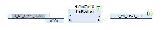
Both PLCs require the same function block called in the program. Under normal operating conditions the elapsed time ET and output Q of the timer is synchronized internally from primary to the secondary CPU. ET and Q data are available and can be attached to local or global variables in the program as per application requirements. If PLC A shuts down due to a fault, the primary status switches over to PLC B.
In the event of a switchover, the moment PLC B becomes the primary, the timer on this PLC will keep running. Until the time of PLC A failure, the timer on PLC B was synchronized. This is most important in cases when one CPU was not in run or off and needs to “catch up” such integral or historic system values (timers, counters, operator settings, …). The actual process remains then unaffected by the switchover.
HA program
HA_MOD_CONTROL has two functions:
-
Exchange status data (lifecom1 and lifecom2) and switch from secondary to primary PLC (or vice versa) based on the status according to the use cases described in 'Failures and use cases'⮫ “Failures and use cases”.
-
Send sync “HA SYNC” array from primary to secondary PLC to ensure that the secondary PLC is always in hot-stand-by and can take over immediately. UDP protocol is used for data synchronization between the CPUs.
Data synchronization via UDP
This chapter explains how the data synchronization happens between primary and secondary PLC via UDP.
All prepared sync data is synchronized with the secondary PLC. Typically only integral values (timers, counters, PID, …) or settings which might have been received have to be synchronized. For example for fast start-up cases when a secondary CPU was restarted, as both PLCs are running and calculating closely in parallel and based on the same input values, synchronization will make the secondary start with current value instead of default value. For details on how to configure or use the data sync function block refer example projects.
Following steps are performed:
-
HA SYNC array is transferred via UDP to the secondary CPU. This includes the exchange of lifecom1 status between primary and secondary CPU.
-
In the HA program the HA_MOD_CONTROL function block collects all diagnosis, sync and lifecom2 data from the field and/ or the other PLC. Whether a switchover is necessary is decided based on a simple decision matrix.
-
Lifecom2 is exchanged between CPUs over Modbus TCP every cycle.
-
One task per program, see figure above.
-
Status of the inputs connected to CI52x decentralized I/O stations is transferred to both PLCs simultaneously in every PLC cycle. They are received by the CI52x function block.
-
At the end of the program, the generated output values are sent, by transferring from the primary PLC respective buffers to the CI52x-MODTCP module(s) via CI52x function block and Modbus TCP. The secondary PLC is prepared to send but stays “silent” (not sending output values).
PLC needs one HA cycle to send one ETH frame data from primary to secondary CPU and receive acknowledge from secondary CPU. Similarly V3 PLC needs two HA cycles.
One ETH frame copies approx. 1412 data bytes. The number of ETH frames needed to synchronize HA Sync Array completely depends on the number of data sync bytes. Global variable iNoOfEthFrames gives the user this information, which should be used to calculate the cycle time for the application task.
⮫ “Task configuration recommendations for HA system”
Up to max. 60 kB of Sync data can be synchronized.
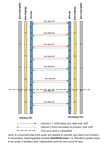
Synchronization between the primary and the secondary PLC happens over a few cycles of HA task time depending on the total sync data bytes configured in the system. Lifecom1 is also exchanged between the primary and the secondary PLC. The primary PLC sends lifecom1 to the secondary PLC along with sync data. Backwards the secondary PLC sends lifecom1 to the primary PLC every cycle.
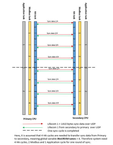
The following figures shows an example for V2 PLC. When in the project the sync data is equal to 4 iNoOfEthFrames then it takes 4 HA cycles to synchronize the data between the PLCs.
When sync data in the project is equal to 6 iNoOfEthFrames then it takes 6 HA cycles to synchronize the data between the PLCs.