


PLC enclosure

NOTICE
PLC damage due to incorrect housing
Due to their construction (degree of protection IP 20 according to EN 60529) and their connection technology, the devices are only suitable for operation in closed control cabinets.
The control cabinet must be suitable to protect the equipment from the following:
-
Unauthorized access.
-
Dusting and contamination.
-
Humidity and moisture.
-
Mechanical damage.
The equipment must be operated within the specified mechanical and enviromental conditions.
Maintain spacing from the following:
-
Enclosure walls.
-
Wireways.
-
Adjacent equipment.
Allow a minimum of 20 mm clearance on all sides. This provides ventilation and galvanic isolation.
It is recommended to mount the modules on an grounded mounting plate, or an grounded DIN rail, independent of the mounting location.
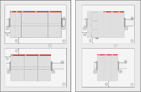
- 1
-
Cable duct
- 2
-
Distance from cable duct ≥20 mm
- 3
-
Mounting plate, grounded
- 4
-
Screw end-stop clamps recommended to avoid movement of the modules on the DIN rail
NOTICE
Horizontal mounting is highly recommended.
Vertical mounting is possible, then derating must be considered to avoid overheating due to poor air circulation.⮫ “Environmental conditions”.
When horizontal mounted, end-stop clamps are recommended to secure the modules in case of shock or vibration.
When vertically mounted, always place an end-stop clamps on the bottom and on the top of the modules to properly secure the modules.