|
This is the web edition of the original ⮫ AC500-S safety user manual, version 1.3.2. This web edition is provided for quick reference only. The original safety user manual must be used to meet functional safety application requirements. |
The input modules can be plugged only on spring-type TU582-S I/O terminal unit. The unique mechanical coding on I/O terminal units prevents a potential mistake of placing the non-safety I/O module on safety I/O terminal unit and the other way around. Basic information on system assembly is shown here.
⮫ “Mechanical planning and installation”
Installation and maintenance have to be performed according to the technical rules, codes and relevant standards, e.g., EN 60204 part 1, by skilled electricians only.
Assembly of AI581-S

DANGER
Hot plug and hot swap of energized modules is not permitted. All power sources (supply and process voltages) must be switched off while working with safety modules.
-
Fig. 448: Assembly instructions 
Put the module on the terminal unit.
The module clicks in.
-
Then press the module with a force of at least 100 N into the terminal unit to achieve proper electrical contact.
Disassembly of AI581-S
-
Fig. 449: Disassembly instructions 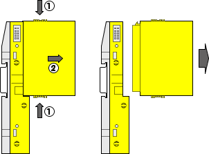
Press above and below, then remove the module.
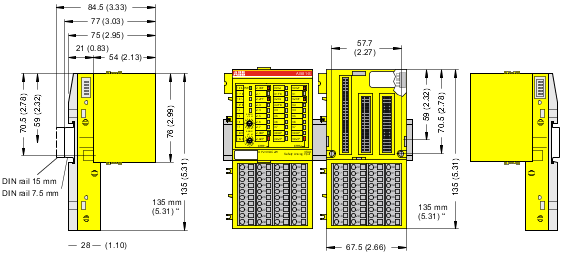
Dimensions
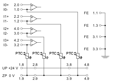
Electrical connection

NOTICE
The same TU582-S is used by all AC500-S safety I/O modules. If TU582-S is wired for DX581-S module with safety digital outputs and DI581-S or AI581-S modules are occasionally placed on this terminal unit, under no circumstances it is possible that safety digital output clamps on TU582-S become energized due to a wrongly placed DI581-S and AI581-S safety I/O modules.
The electrical connection of the I/O channels is carried out using 40 terminals of the I/O terminal unit. I/O modules can be replaced without re-wiring the terminal units.
The terminals 1.8, 2.8, 3.8 and 4.8 as well as 1.9, 2.9, 3.9 and 4.9 are electrically interconnected within the I/O terminal unit and have always the same assignment, independent of the inserted module:
-
Terminals 1.8, 2.8, 3.8 and 4.8: Process voltage UP = +24 V DC
-
Terminals 1.9, 2.9, 3.9 and 4.9: Process voltage ZP = 0 V
The assignment of the other terminals:
|
Terminals |
Signal |
Meaning |
|---|---|---|
|
1.0, 1.2, 3.0, 3.2 |
I0-, I1-, I2-, I3- |
Negative connectors of 4 analog inputs |
|
2.0, 2.2, 4.0, 4.2 |
I0+, I1+, I2+, I3+ |
Positive connectors of 4 analog inputs |
|
1.1, 1.3, 3.1, 3.3 |
FE |
Functional earth |
|
1.8, 2.8, 3.8, 4.8 |
UP |
Process power supply +24 V DC |
|
1.9, 2.9, 3.9, 4.9 |
ZP |
Central process earth |
|
1.4 ... 1.7, 2.1, 2.3 ... 2.7, 3.4 ... 3.7, 4.1, 4.3 ... 4.7 |
Free |
Not used |
NOTICE
The process voltage must be included in the earthing concept of the control system (e.g., earthing the minus pole).
NOTICE
The minus poles of the analog inputs are electrically connected to each other. They form an "analog ground" signal for the module.
Because of their common reference potential, analog current inputs cannot be circuited in series, neither within the module nor with channels of other modules.
NOTICE
There is no electrical isolation between the analog circuitry and ZP/UP. Therefore, analog sensors must be electrically isolated in order to avoid loops via the earth potential or supply voltage.
NOTICE
Analog signals are always laid in shielded cables. The cable shields are earthed at both ends of the cables. In order to avoid unacceptable potential differences between different parts of the installation, low resistance equipotential bonding conductors must be laid.
For simple applications (low disturbances, no high requirement on precision), the shielding can also be omitted.
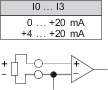
Examples of connections
Examples of electrical connections with AI581-S module and single channels Ix.
NOTICE
The PTC shown in the connection diagram is built-in in AI581-S module.