


This communication schema is only available for PM56xx PLCs supporting communication modules.
The communication schema “Communication modules” is intended for users of a communication module which can be configured to synchronize its stack activity with the user application by a dedicated (external event triggered IEC task) which is mapped to an event (“CouplerEventX”, X = slot number of the communication module).
The bus synchronized IEC task is not scheduled by the PLC runtime system but the stack of the communication module. As a result of this, it’s necessary for the PLC to quickly react on the related event of the communication module. The schema ensures that negative side-effects on the bus synchronized IEC task are reduced as much as possible by adjusting priorities of high priority functionality.
Features and their priorities
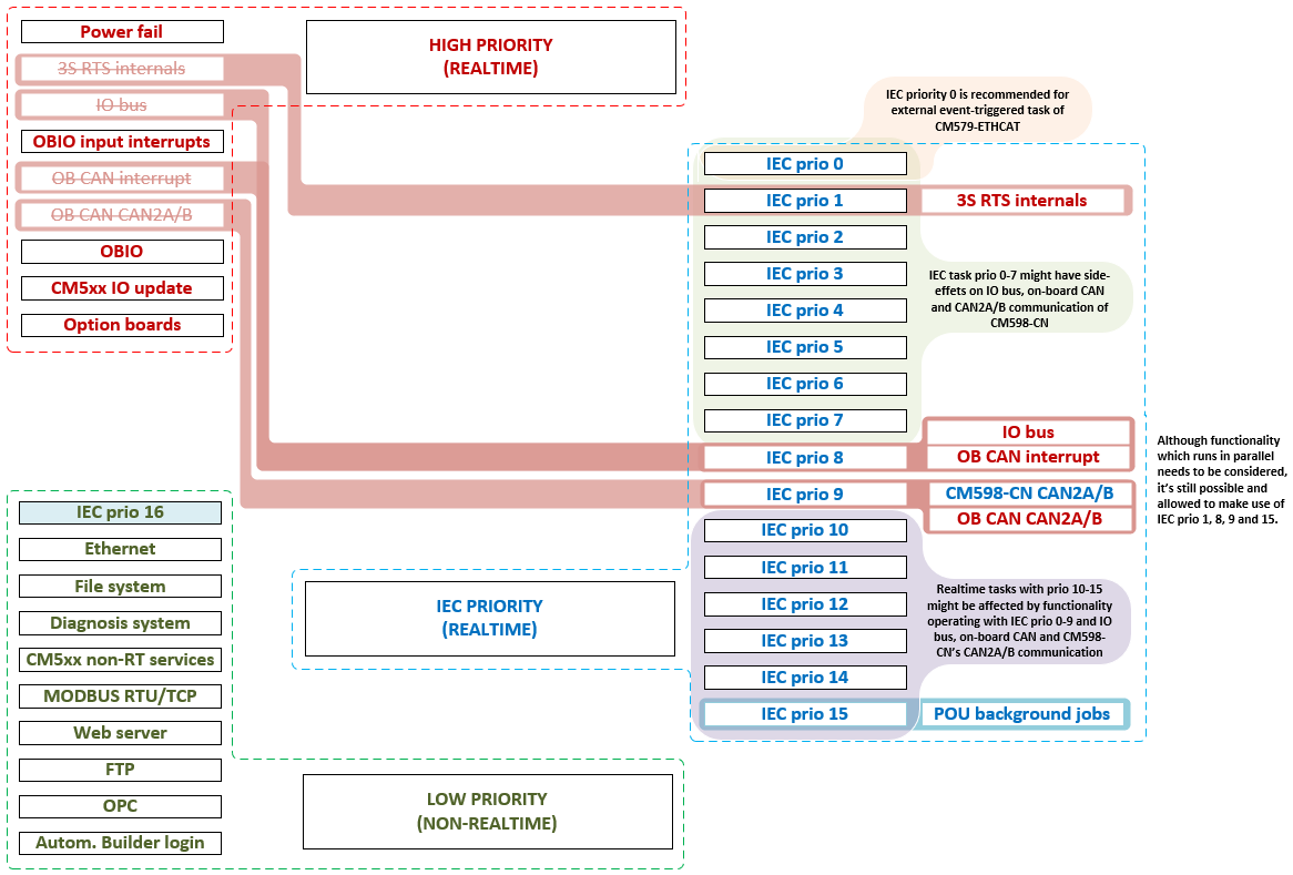
The following figure shows the changes the schema applies to the available features of the PLC. The primary goal of this schema is to reduce the number of tasks which are capable of interrupting or delaying the bus synchronized IEC task, while providing as much flexibility as possible. By making use of the priority range of IEC tasks, users can decide whether existing IEC tasks will influence the corresponding features.
-
Use IEC priority 0 for the bus synchronized IEC task and a priority lower than 0. For all other features to avoid negative side-effects on the bus synchronized IEC task.
-
Use IEC priorities 1 to 5 for functionality which is more important than high priority features like IO bus or CAN.
-
To ensure that a high priority feature is not influenced by any IEC user code (besides of the bus synchronized IEC task), use an IEC task priority which is lower than the priority of the corresponding feature.
It is not forbidden to make use of IEC task priorities which are assigned to other PLC functionality.

NOTICE
Be careful when using this schema to avoid unwanted side-effects on features besides of the protocol realized by the corresponding communication module, caused by violation of individual timing constraints or requirements!
I/O bus must be able to refresh all connected S500 I/O devices within 20 ms. Otherwise, an exception will be raised which will lead to a
stop of the application. Use PLC shell command io-bus desc to dump information on the bus timing. The output contains information on the IO
bus cycle time:
--- I/O bus information —
Baud rate [baud]: 1714286
Min. cycle time [us]: 1037
Max. cycle time [us]: 10936
Last cycle time [us]: 1567
The maximum cycle time must be below 20 ms to ensure that the system runs stable and won’t raise a timeout exception error.
If the cycle time reaches the limit, try to reduce the amount of code executed by IEC user tasks of higher priority than I/O bus or adjust task priorities if possible.