

|
This is the web edition of the original ⮫ AC500-S safety user manual, version 1.3.2. This web edition is provided for quick reference only. The original safety user manual must be used to meet functional safety application requirements. |
The setting of two rotary switches for PROFIsafe address and/or system configuration (for example, these switches can be used for safety program flow control) can be read out in the safety application program using POU SF_SM5XX_OWN_ADR⮫ “SF_SM5XX_OWN_ADR”. Switch address values 0xFF, 0xFE, 0xFD and 0xFC are used for internal safety CPU system functions described below:
-
Switch address value 0xFF during the start of the safety CPU prevents loading the boot project to the safety CPU on start-up (the boot project still remains in the flash memory of the safety CPU). As a result, the user is able to log-in to the safety CPU and load a new correct boot project. This can be needed if the boot project is corrupt and could lead to a SAFE STOP state of the safety CPU. The safety CPU goes to DEBUG STOP (non-safety) state after start-up and successful 0xFF command execution.
-
Switch address value 0xFE during the start of the safety CPU allows deleting the boot project from its flash memory. The boot project is finally deleted after a power cycle of the safety CPU. This can be needed if the boot project is corrupt and could lead to a SAFE STOP state of the safety CPU. The safety CPU goes to SAFE STOP state after start-up and 0xFE command execution.
-
Switch address value 0xFD during the start of the safety CPU allows deleting user data from its flash memory. The user data are finally deleted after a power cycle of the safety CPU. This can be needed if user data are corrupt and could lead to a SAFE STOP state of the safety CPU. The safety CPU goes to SAFE STOP state after start-up and 0xFD command execution.
-
Switch address value 0xFC during the start of the safety CPU allows deleting all safety CPU data, which includes, in addition to boot project and user data, also safety CPU password and defined power dip value from the flash memory. This means that the safety CPU will be brought to its original state. The data is finally deleted after a power cycle of the safety CPU. The safety CPU goes to SAFE STOP state after start-up and 0xFC command execution.
The switch address value range 0xF0 ... 0xFB is reserved for future internal system functions.

NOTICE
Usage of switch address values from the system range 0xF0 ... 0xFF can lead to the loss of important user information in the flash memory of the safety CPU, e.g., boot project, user data, password or power dip value can be lost. Therefore, it is important that users pay a special attention during the change of switch address position on the safety CPU.

DANGER
Despite the fact that SF_SM5XX_OWN_ADR function is a safety POU, the hardware switch address value is a non-safety value and needs additional measures to satisfy functional safety requirements.
PROFIsafe F_Dest_Add addresses for F-Devices on SM560-S-FD-1 / SM560-S-FD-4 safety CPUs are defined using the rotary address switch. It means that the rotary address switch on safety CPUs can have more than one function behind. This shall be carefully considered during the safety application design, for example, if system functions (0xFF, 0xFE, 0xFD and 0xFC values on the rotary address switch) have to be used on SM560-S-FD-1 / SM560-S-FD-4 safety CPUs. In the latter case, the previously defined rotary address switch value for F_Dest_Add addresses shall be properly documented and set back to its original documented value after system functions on the safety CPU were successfully performed.
Usage of the rotary address switch for F_Dest_Add setting allows using the same safety CPU boot project for different machines provided that each machine will have a unique pre-set F_Dest_Add address defined with the rotary address switch and properly engineered in Automation Builder project.
The allowed range of the rotary address switch value for F_Dest_Add setting is 1 to 239 (0 would indicate no usage of F-Devices on SM560-S-FD-1 / SM560-S-FD-4). One rotary address switch represents F_Dest_Add for all possible F-Device instances (maximum 32 F-Device instances each with 12 bytes of safety data) on SM560-S-FD-1 / SM560-S-FD-4 safety CPUs.
The following rule applies for F_Dest_Add assignment to F-Devices:
-
F_Dest_Add for F-Device = Rotary address switch value * 100 + F-Device instance number (0..31, which is the consecutive number as F-Devices are instantiated in Automation Builder module/device tree).
-
To properly configure F-Device on SM560-S-FD-1 and SM560-S-FD-4 safety CPUs, one has to provide the correct configuration of F_Dest_Add using the rotary address switch value and F- Parameter configuration provided from F-Host and its controller.
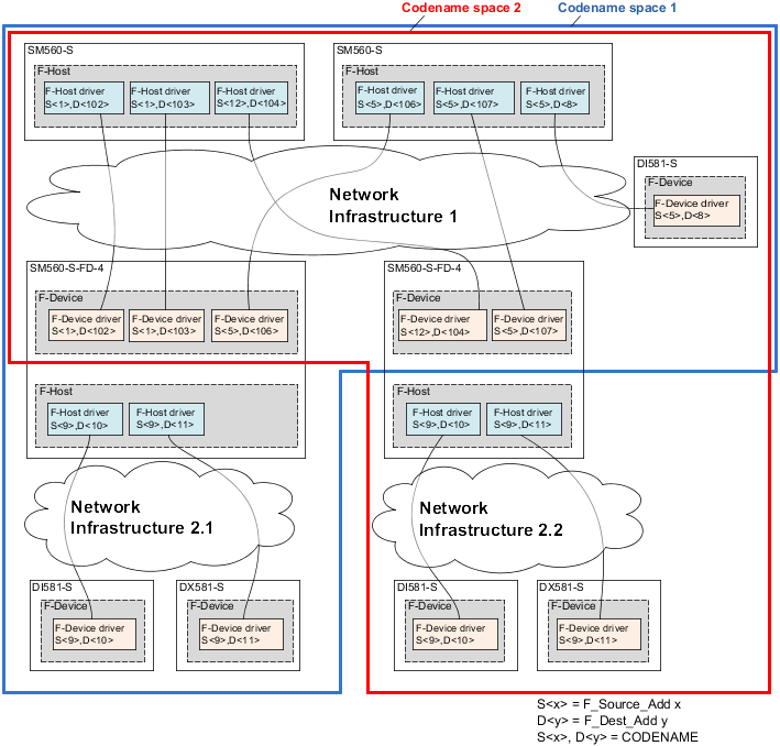
A complex system containing multiple AC500-S sub-systems connected together via PROFIsafe needs some additional consideration on how to allocate F_Dest_Add and F_Source_Add addresses because messages from different F-Hosts can overlap in the "Black Channel", for example in non-safety CPU. The potential overlapping may increase the probability of dangerous error in the safety configuration and communication. The typical PFH value for PROFIsafe communication is 3.0E-10.
DANGER
For each AC500-S sub-system, which PROFIsafe communication can overlap in the "Black Channel" with the PROFIsafe communication from another F-Host, a pair of F_Dest_Add and F_Source_Add (so-called codename in PROFIsafe terminology⮫ [2]) have to be unique. If only F_Dest_Add is checked by the F-Device (e.g., using hardware address settings on it), then not only codenames but also F_Dest_Add shall be unique. In case of SM560-S-FD-1 and SM560-S-FD-4, due to the fact that PROFIsafe communication from different F-Hosts (PROFIsafe telegrams from own F-Host on SM560-S-FD-1 or SM560-S-FD-4 and PROFIsafe telegrams from external F-Hosts) will overlap on non-safety CPU, additional measures to unique codenames shall be applied:
-
Unique F_Dest_Add for all F-Devices belonging to external F-Host(s) and own F-Host on SM560-S-FD-1 or SM560-S-FD-4 safety CPUs.
NOTICE
FSCP 3/1 address type 1 is used in SM560-S-FD-1 and SM560-S-FD-4:
Only F_Dest_Add is used for PROFIsafe F-Device identification in SM560-S-FD-1 and SM560-S-FD-4.
The allowed range for F_Dest_Add addresses is described in⮫ “Instantiation and configuration of safety modules / definition of variable names”.
DANGER
As a summary, the following rules shall be applied using organizational procedures for safe CPU to CPU communication using SM560-S-FD-1 and SM560-S-FD-4 CPUs. (This has to be checked manually and is a part of⮫ “Checklist for configuration and wiring”.):
-
In the same codename space, F_Dest_Add shall be unique (Fig.402).
-
In the same codename space, F_Source_Add shall not be re-used in other F-Hosts. Inside the same F-Host, a re-use is allowed for several F-Host drivers.
-
In the same codename space, F_Dest_Add shall not be used as F_Source_Add and vice versa.
To ensure that the right safety configuration and safety application is loaded to the right system, customers can use SM560-S-FD-1 / SM560-S-FD-4 address switch to verify that the configuration fits to the selected system. The address switch on SM560-S-FD-1 / SM560-S-FD-4 implicitly protects the given safety CPU because it is used for the definition of F_Dest_Add for PROFIsafe F-Device instances. If a wrong boot project is loaded on the given SM560-S-FD-1 / SM560-S-FD-4, then it will not match to F- Parameters transferred from the F-Host and will end in the configuration error of the corresponding PROFIsafe instance.