


|
This is the web edition of the original ⮫ AC500-S safety user manual, version 1.3.2. This web edition is provided for quick reference only. The original safety user manual must be used to meet functional safety application requirements. |
- Personnel:
-
-
Safety application engineer of AC500-S safety PLC
Commissioning and operation of AC500-S safety PLC may only be performed by the qualified personnel who is authorized to commission safety devices, systems and circuits in accordance with established functional safety practices and standards.
The following basic knowledge of AC500 system is required to correctly understand this AC500-S safety user manual:
-
AC500 automation system.
-
Automation Builder / Control Builder Plus programming environment (system configuration and programming in ST, LAD and FBD programming languages).
-
-
-
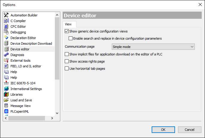
In Automation Builder, go to “Tools Options...”. Activate “Show generic device configuration views” and instantiate a given type of safety I/O module (AI581-S, DI581-S or DX581-S) in the Automation Builder tree (DX581-S is used as an example):
-
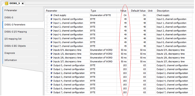
Go to the iParameter setting tab (“DX581-S”, “DI581-S” or “AI581-S”) for the given module and set appropriate iParameter values (e.g., “Test Pulse”, “Input Delay”, etc.).
-
Verify against your safety application technical specification that all iParameters for all safety I/O channels are set correctly.
-
Go to “F-Parameter” tab and press [Calculate] button. Copy calculated F_iPar_CRC value from the “Checksum iParameter” field and paste it to “F_iPar_CRC” field of the F-Parameter editor.
-
Go to “<safety I/O module name> Parameters” tab, and verify using a cross-check according to⮫ “ Verification tables for iParameter settings in AC500-S safety I/Os” that iParameter settings previously set at Step 2 are the same as ones listed in the “Value” column for given channels (use⮫ “ Verification tables for iParameter settings in AC500-S safety I/Os” to decode integer values to real parameter values).
-
Go to “F-Parameter” tab and press [Calculate] button once more, even if the previous value is still available. Compare that the value shown in “Checksum iParameter” field and the one in F_iPar_CRC field of the F-Parameter editor are the same.
If F_iPar_CRC values are the same, then the verification procedure for given iParameter settings of the given AC500-S safety I/O module was successfully passed.
Important!
-
If any errors (F_iPar_CRC or iParameters are not equal) were identified during Steps 1 ... 6, then one has to re-do the same procedure from the beginning. If after this second repetition there is still inconsistency, contact ABB technical support for help.
-
Note, if iParameters values were verified as described in Steps 1 ... 6, you can re-use this iParameter combination with the given F_iPar_CRC for further modules of the same type without repeating the verification procedure described above.