


Due to the broad variety of functionality which can run in parallel on AC500 PLCs, it is recommended, or even mandatory depending on the desired functionality, to adjust system behavior to better match the needs of the individual application.
Due to hardware limitations and constraints, it’s necessary to prioritize functionality, especially if it’s intended to execute multiple features in parallel. Prioritizing can be very difficult due to the complexity of the underlying software components. Besides of task priorities, it might also be necessary to adjust low level system configuration to achieve the best possible performance for a specific feature.
To reduce complexity, and thus the risk of negative side-effects the CPU parameter
Communication schema has been introduced. This parameter enables the user to specifically define the primary
purpose of the corresponding PLC and lay focus on a specific functionality.
|
Schema |
PM50xx |
PM56xx |
Description |
|---|---|---|---|
|
Default |
X |
X |
Balanced priority for communication via communication modules (CMs) and onboard Ethernet communication. |
|
Communication modules |
- |
X |
Priority and high performance for communication module (CM) based communication via sync tasks. Lower priority for onboard Ethernet and I/O bus. |
|
Onboard Ethernet |
X |
X |
Priority and high performance for communication module (CM) based communication via sync tasks. Lower priority for onboard Ethernet and I/O bus. |
|
Onboard EtherCAT ⮫ “Communication schema “Onboard EtherCAT” since “SystemFW” 3.4.1” |
X |
X |
Very high priority for onboard Ethernet communication (e. g. EtherCAT, PROFINET, EtherNet/IP). Low priority for communication via communication modules (CMs). |
Changing communication schema might have significant impact on the behavior of the user application and should therefore only be done if,
-
a feature is configured which relies on a specific schema (e.g., onboard EtherCAT).
-
there’s need of optimization of system behavior in terms of performance (decrease of reaction times, increase of throughput etc.).
Note that the increase of flexibility and freedom comes with an increase of responsibility because IEC task configuration and IEC user code might block important system functionality for too long. The following provided information should help to identify appropriate settings to prevent runtime errors like timeout exceptions or communication problems.
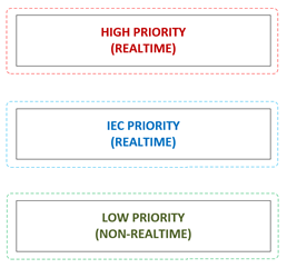
Priority classifications and their purpose
The functionality prioritized by each communication schema is grouped into 3 different classes:
-
High priority real-time functionality
-
IEC tasks with real-time priority
-
Low priority non-real-time functionality
High priority real-time functionality
Functionality with strict timing requirements, e.g., drivers with hardware access or hardware watchdog monitoring failures might lead to exception errors, loss of communication with hardware and other problems which are non-recoverable and might cause a stop of the user application.
Functionality of this class can’t be influenced by activity of user defined IEC tasks. As a result of this, related functionality can interrupt or delay IEC tasks and therefore increase IEC task jitter and the duration of IEC task cycles.
IEC tasks with real-time priority
This is the priority range of user defined real-time IEC tasks. Priorities 0 to 15 are real-time priorities (IEC priority 16 is mapped to non-real-time priority) and can be used to define an IEC task’s priority in Automation Builder.
Task in this range can be interrupted or delayed by high priority functionality. It’s not possible for IEC user code to suppress high priority activity, thus increasing safety and reducing the risk of negative side effects caused by bugs in IEC user code or libraries or misconfiguration of IEC tasks.
Low priority non-real-time functionality
The low priority range is intended for non-real-time functionality which doesn’t have any specific timing requirements and which is supposed to execute its activity without delaying or interrupting the user application and its related functionality.
Activity assigned to this range can be suppressed by high priority and real-time IEC tasks. Therefore might show high jitter, sporadic activity or large reaction times, depending on the overall system load.
To avoid suppression of the tasks of this group, the system reserves a short time slot to process low-priority functionality if the CPU load reaches nearly 100%. Under normal circumstances (below an average system load of 80%), this mechanism shouldn’t be engaged. Although this time slot could cause high priority tasks to jitter slightly (± 100 microseconds), it ensures that the system remains responsive and will always be able to run fundamental jobs which must be executed regularly. Note that tasks of low priority still play an important role and need to be scheduled regularly to meet their individual timing requirements.
Ensure that the average CPU load doesn’t exceed 80% to ensure that there’s enough time for the system to process low-priority functionality.
The functionality might not be important for the individual application, but it is still necessary to keep alive other functionality like the Automation Builder login or access to diagnosis data.
Once the CPU load exceeds 80%, it will be difficult for the system to correctly schedule tasks.